Wear-resistant and corrosion-resistant rubber lining slurry pump
A slurry pump and rubber-lined technology, which is applied in the direction of pumps, pump components, pump devices, etc., can solve the problems of insufficient sealing effect and affecting the normal use of equipment, so as to reduce the work burden, prevent dust from entering the inside of the equipment, and increase the lift. Effect
- Summary
- Abstract
- Description
- Claims
- Application Information
AI Technical Summary
Problems solved by technology
Method used
Image
Examples
Embodiment 1
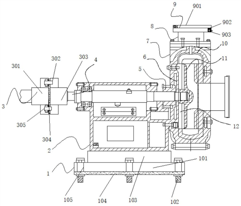
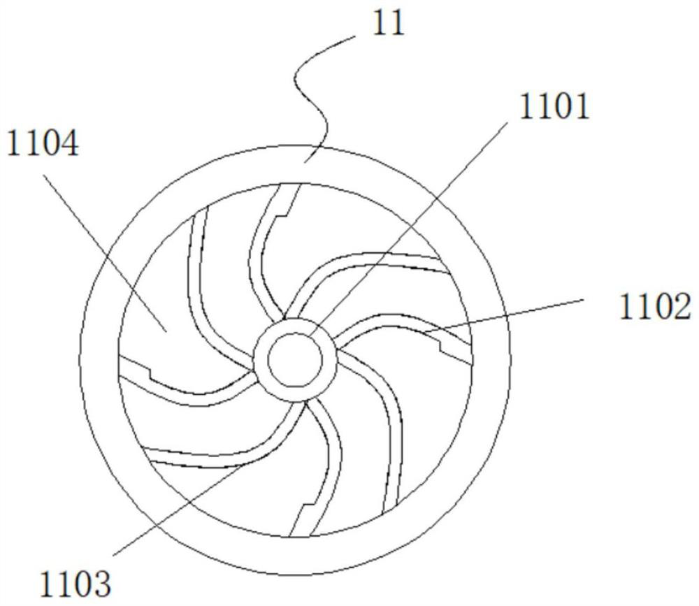
[0035] Example 1: See Figure 1-6 , a wear-resistant and corrosion-resistant rubber-lined slurry pump, including a bracket 2 and a pump body 7, a fixed installation structure 1 is arranged at the bottom of the bracket 2, a bearing 4 is arranged inside the top of the bracket 2, and one side of the bearing 4 is arranged There is a quick connection structure 3, the other side of the bearing 4 is provided with a pump body 7, the top of the pump body 7 is fixedly connected to the short tube 8, the top of the short tube 8 is provided with a protective structure 9, and the top and bottom ends of the pump body 7 are Both are provided with a pump cover sheath 10, an energy-saving structure 11 is provided at the middle position inside the pump body 7, and a sealing structure is provided at one side inside the pump body 7;
[0036] see Figure 1-6 The wear-resistant and corrosion-resistant lining rubber slurry pump also includes a sealing structure. The sealing structure includes a stuf...
Embodiment 2
[0039] Embodiment 2: The fixed installation structure 1 is made up of connecting seat 101, fixing bolt 102, base 103, anti-skid pad 104 and through groove 105, and base 103 is fixedly connected to the bottom end of bracket 2, and the bottom end of base 103 is fixedly connected with connection Seat 101, the inside of connecting seat 101 is fixedly connected with through grooves 105 around the inside, the lengths of the through grooves 105 are all equal, the through grooves 105 are arranged at equal intervals inside the connecting seat 101, and the inside of the through grooves 105 are all provided with fixing bolts 102, the bottom end of the connection seat 101 is fixedly connected with a non-slip pad 104;
[0040] Specifically, such as figure 1 with Figure 5 As shown, after placing the device at the designated location, install it fixedly, place the connecting seat 101 above the hole dug in advance, adjust the position of the connecting seat 101, and overlap the anti-skid pa...
Embodiment 3
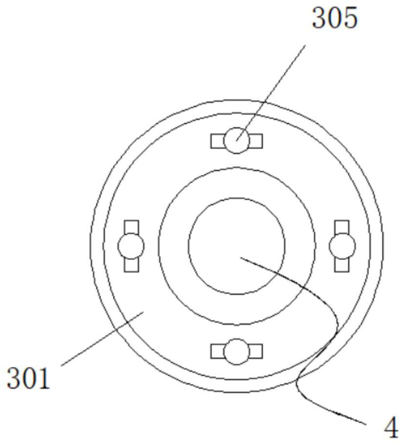
[0041] Embodiment 3: The quick connection structure 3 is composed of a left limiting seat 301, a block 302, a right limiting seat 303, a sealing ring 304 and a card groove 305. The right limiting seat 303 is fixedly connected to one side of the bearing 4, and the right limiting seat 303 Blocks 302 are fixedly connected around the outside of the seat 303, a left limit seat 301 is provided on one side of the right limit seat 303, and a draw-in slot 305 is fixedly connected around the inside of the left limit seat 301, and the inside of the draw-in slot 305 The width is greater than the width outside the clamping block 302, the inside of the clamping groove 305 is embedded with the clamping block 302, and a sealing ring 304 is arranged between the right limiting seat 303 and the left limiting seat 301;
[0042] Specifically, such as figure 1 with image 3 As shown, when the device needs to be connected with the motor, the device is connected to the motor through the right limit ...
PUM
 Abstract
Description
Claims
Application Information
 - Generate Ideas
- Intellectual Property
- Life Sciences
- Materials
- Tech Scout
- Unparalleled Data Quality
- Higher Quality Content
- 60% Fewer Hallucinations
Browse by: Latest US Patents, China's latest patents, Technical Efficacy Thesaurus, Application Domain, Technology Topic, Popular Technical Reports.
© 2025 PatSnap. All rights reserved.Legal|Privacy policy|Modern Slavery Act Transparency Statement|Sitemap|About US| Contact US: help@patsnap.com


