
Carding machine with device for detecting interfering particles

A carding machine and particle technology, which is applied in the field of carding machines, can solve the problems of easy failure and consumption, and achieve the effects of avoiding failure, long service life and shortening downtime

Pending Publication Date: 2020-12-08
特吕茨施勒集团欧洲公司
View PDF13 Cites 0 Cited by
  • Summary
  • Abstract
  • Description
  • Claims
  • Application Information

AI Technical Summary

Problems solved by technology

Another disadvantage is the moveable arrangement of the sensor in the web-guiding profile, which is rather expensive to set up and prone to failure due to cables dragged during the movement of the sensor

Method used


Image

  • Carding machine with device for detecting interfering particles
  • Carding machine with device for detecting interfering particles
  • Carding machine with device for detecting interfering particles

Examples


Embodiment Construction

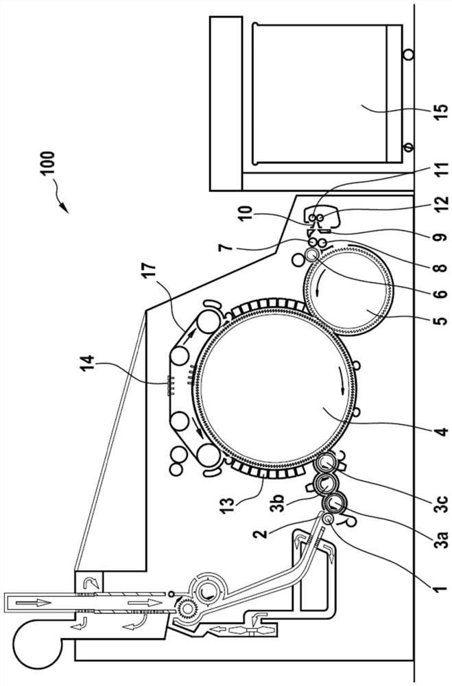
[0023] figure 1 A card 100 according to the prior art is shown in which the fiber bundles are guided through channels to a feed roller 1 , a feed plate 2 , through a plurality of licker-in rollers 3 a , 3 b , 3 c to a drum 4 or cylinder. On the drum 4, the fibers of the fiber bundles are decomposed by means of fixed carding elements 13, deflation hoods and chopping knives, as well as by means of carding elements arranged in circulation on a revolving flat system 17 and formed as flat strips 14. The fibers are parallelized and cleaned. The resulting fibrous web 16 is then transported via a doffer 5, stripping rollers 6 and a plurality of squeeze rollers 7, 8 to a web guiding element 9, which converts the fibrous web into fibers by means of a web collecting bell 10. The fiber strips are transferred to subsequent processing equipment or cans 15 via detaching rollers 11 , 12 . The flat strip 14 and the carding elements 13 are adjusted relative to the cylinder 4 (carding nip) by ...


PUM


Abstract

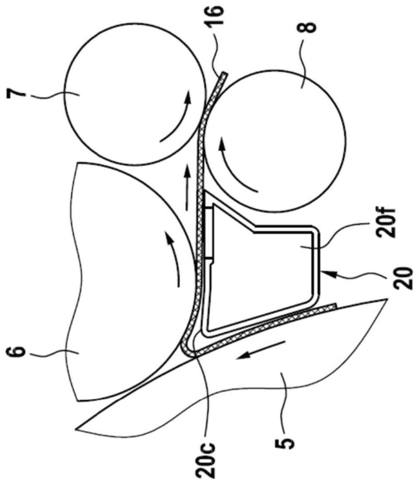
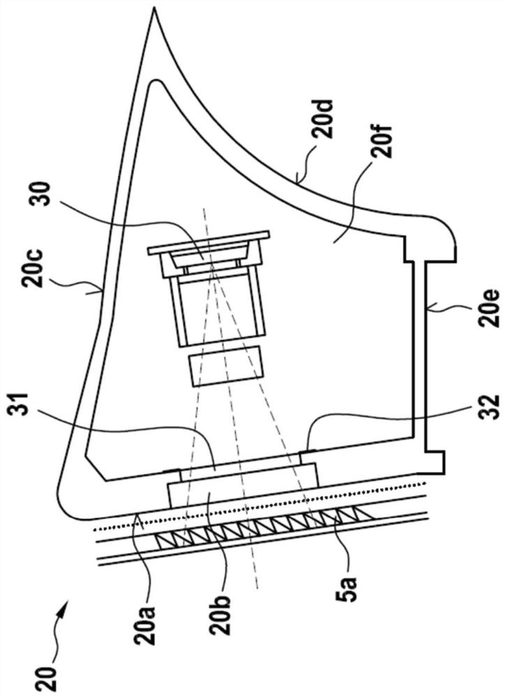
The invention relates to a carding machine (100) having a device for detecting interfering particles, in particular waste parts, agglomerates, crumbs, slubs and / or impurities in a carded fibrous web (16), said device comprising at least one sensor (30) arranged in a web guide element (20), wherein the web guide element (20) is arranged in the transition of the doffer (5) to the stripping roller (6), and wherein the at least one sensor (30) detects the fibrous web (16) on the doffer (5).

Description

technical field [0001] The invention relates to a carding machine with a device for detecting interfering particles, in particular waste fractions, agglomerates, husks, slubs and / or impurities in a carded fibrous web, wherein , the device has at least one sensor. Background technique [0002] In the field of textile technology, it is known from the prior art to detect clumps, interfering particles or dirt particles in fiber webs, fiber strands or threads. The known methods differ in the accuracy of the determined values ​​and in the reliability in the daily operation of the spinning, since the individual components have to function permanently well in very dirty and thermally loaded conditions. The detection of clumping or fiber knots can be carried out in different ways in the unfolded fiber web or in the fiber strip. A very large number of measuring devices is required when detecting fiber slivers, since it is generally not possible to see the inside of the fiber sliver ...

Claims


Application Information

Patent Timeline
IPC IPC(8): D01G15/82D01G15/12
CPCD01G15/82D01G15/12D01G31/003
Inventor 克里斯托夫·莱德斯约尔根·马尔奇
Owner 特吕茨施勒集团欧洲公司
Learn More