
Steel wire rope dip-coating and oiling device and using method thereof

An oiling device and steel wire rope technology, which is applied to the surface coating liquid device, coating, grinding machine, etc., can solve the problem of shortening the time for liquid oil to protect the steel wire rope, increasing the difficulty of internal components of the oiling device, and reducing the oiling device. Convenience and other issues to achieve the effect of shortening the protection time, improving convenience and improving the effect

Pending Publication Date: 2020-12-08
山东固丝德夫金属制品有限公司
View PDF1 Cites 0 Cited by
  • Summary
  • Abstract
  • Description
  • Claims
  • Application Information

AI Technical Summary

Problems solved by technology

[0003] At present, there are still some deficiencies in the existing steel wire rope immersion oiling device, for example; The stains are easy to fuse with the oil, thus shortening the time for liquid oil to protect the steel wire rope and reducing the effect of the steel wire rope during maintenance. Moreover, the existing steel wire rope dipping and oiling device adopts a structure that is installed and fixed as a whole or bolts, which slows down The speed of the operator when disassembling and assembling the oiling device increases the difficulty for the operator to replace or repair the internal parts of the oiling device, and reduces the convenience of disassembling and assembling the oiling device

Method used


Image

  • Steel wire rope dip-coating and oiling device and using method thereof
  • Steel wire rope dip-coating and oiling device and using method thereof
  • Steel wire rope dip-coating and oiling device and using method thereof

Examples


Embodiment Construction

[0029] The following will clearly and completely describe the technical solutions in the embodiments of the present invention with reference to the accompanying drawings in the embodiments of the present invention. Obviously, the described embodiments are only some, not all, embodiments of the present invention.

[0030] In describing the present invention, it should be understood that the terms "upper", "lower", "front", "rear", "left", "right", "top", "bottom", "inner", " The orientation or positional relationship indicated by "outside", etc. is based on the orientation or positional relationship shown in the drawings, and is only for the convenience of describing the present invention and simplifying the description, rather than indicating or implying that the referred device or element must have a specific orientation, so as to Specific orientation configurations and operations, therefore, are not to be construed as limitations on the invention.

[0031] see Figure 1-Fig...


PUM


Abstract

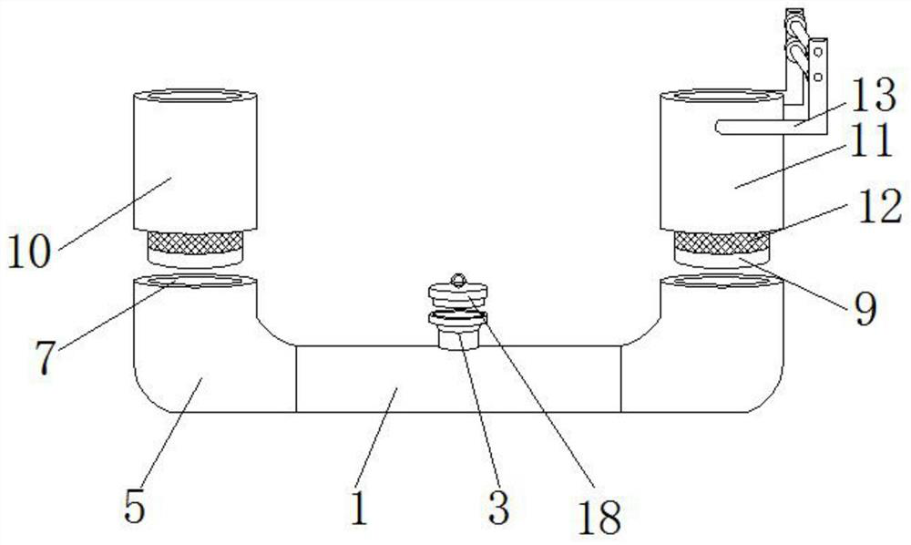
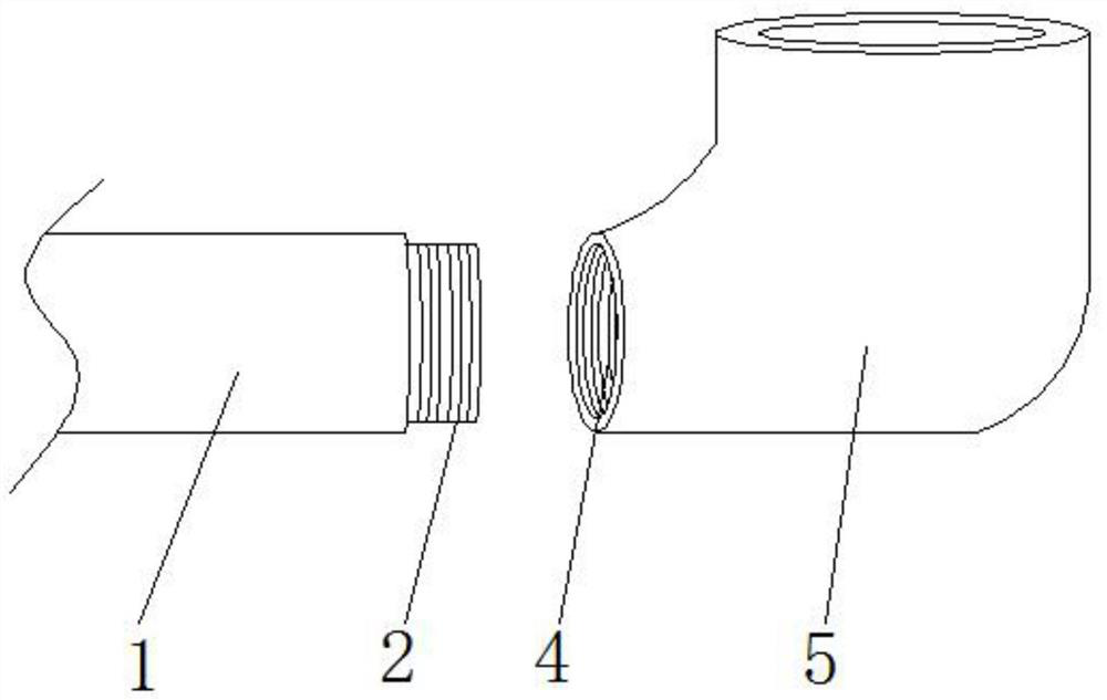
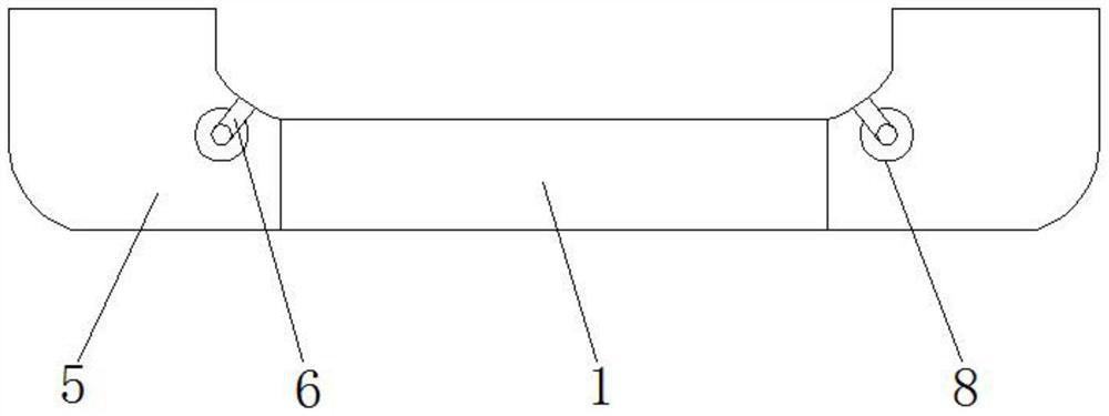
The invention discloses a steel wire rope dip-coating and oiling device and a using method thereof. The steel wire rope dip-coating and oiling device structurally comprises an oil storage pipe, threaded connectors and an oil injection hopper are arranged on the oil storage pipe, the threaded connectors are welded to the two ends of the oil storage pipe and communicate with the interior of the oilstorage pipe, and the oil injection hopper is welded to the middle of the upper end of the oil storage pipe and communicates with the interior of the oil storage pipe; the threaded connectors are connected with bent pipes through threaded grooves, the bent pipes are provided with U-shaped supporting rods and embedding grooves, the U-shaped supporting rods are welded to the inner walls of the bentpipes, and the embedding grooves are located in the upper portions of the interiors of the bent pipes; and first I-shaped guide wheels are arranged on the U-shaped supporting rods. According to the steel wire rope dip-coating and oiling device, rust stains on the surface of a steel wire rope can be cleaned before the steel wire rope is coated with oil, and the rust stains are prevented from beingmixed with oil after the steel wire rope is coated with oil, so that the time of protecting the steel wire rope by liquid oil is shortened, and the maintenance effect of the steel wire rope is improved.

Description

technical field [0001] The invention relates to the technical field of oiling devices, in particular to a steel wire rope immersion oiling device and a method for using the same. Background technique [0002] According to the patent 201921259488.4, a steel wire rope immersion oiling device includes an oil storage pipe, both ends of the oil storage pipe are welded with elbows, and the tops of the two sets of elbows are respectively welded with a first pipe and a second pipe, The upper ends of the first pipe and the second pipe are rotatably installed with first guide wheels, and the inner corners of the two groups of elbows are equipped with second guide wheels, and the inner sides of the first pipes are welded with support columns. One end of the support column is welded with a fixed splint. In the utility model, the first pipe and the second pipe are welded at both ends of the oil storage pipe through elbows, the first guide wheel and the second guide wheel are respectivel...

Claims


Application Information

Patent Timeline
IPC IPC(8): B05C9/10B05C3/12B05C13/02B05D3/12B24B27/00B24B27/033
CPCB05C9/10B05C3/125B05C13/02B05D3/12B24B27/033B24B27/0076
Inventor 胡范芝李长明朱小云马帅周易
Owner 山东固丝德夫金属制品有限公司
Learn More