
Automatic food processor

A food processing machine and automatic technology, which is applied in home appliances, applications, kitchen appliances, etc., can solve problems such as increased noise, accelerated motor vibration, and reduced consumer experience, so as to achieve the effect of improving crushing efficiency and improving user experience

Active Publication Date: 2020-12-08
JOYOUNG CO LTD
View PDF11 Cites 0 Cited by
  • Summary
  • Abstract
  • Description
  • Claims
  • Application Information

AI Technical Summary

Problems solved by technology

Although increasing the motor speed can indeed further improve the crushing efficiency, it also brings about the acceleration of the motor vibration, and the noise of the soybean milk machine is further increased, and the consumer's experience is reduced.

Method used


Image

  • Automatic food processor
  • Automatic food processor
  • Automatic food processor

Examples


Embodiment 1

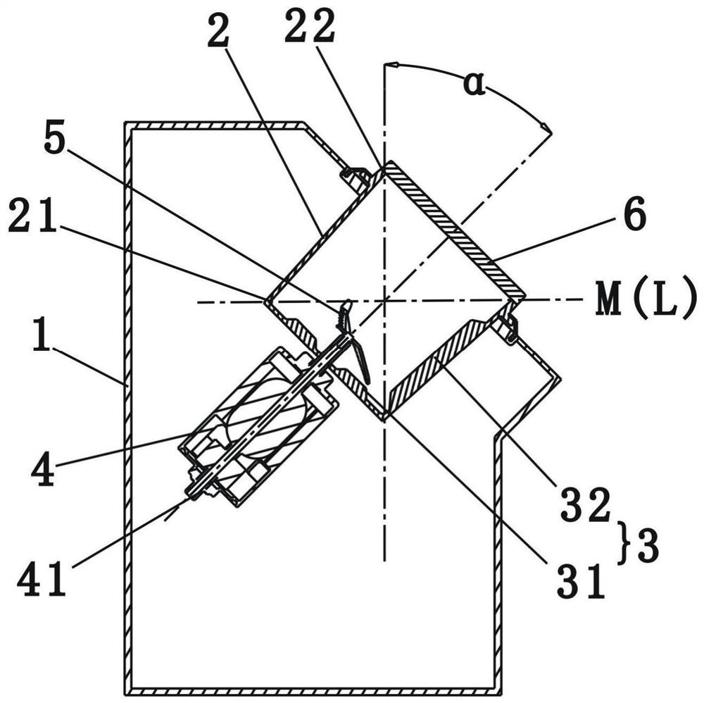
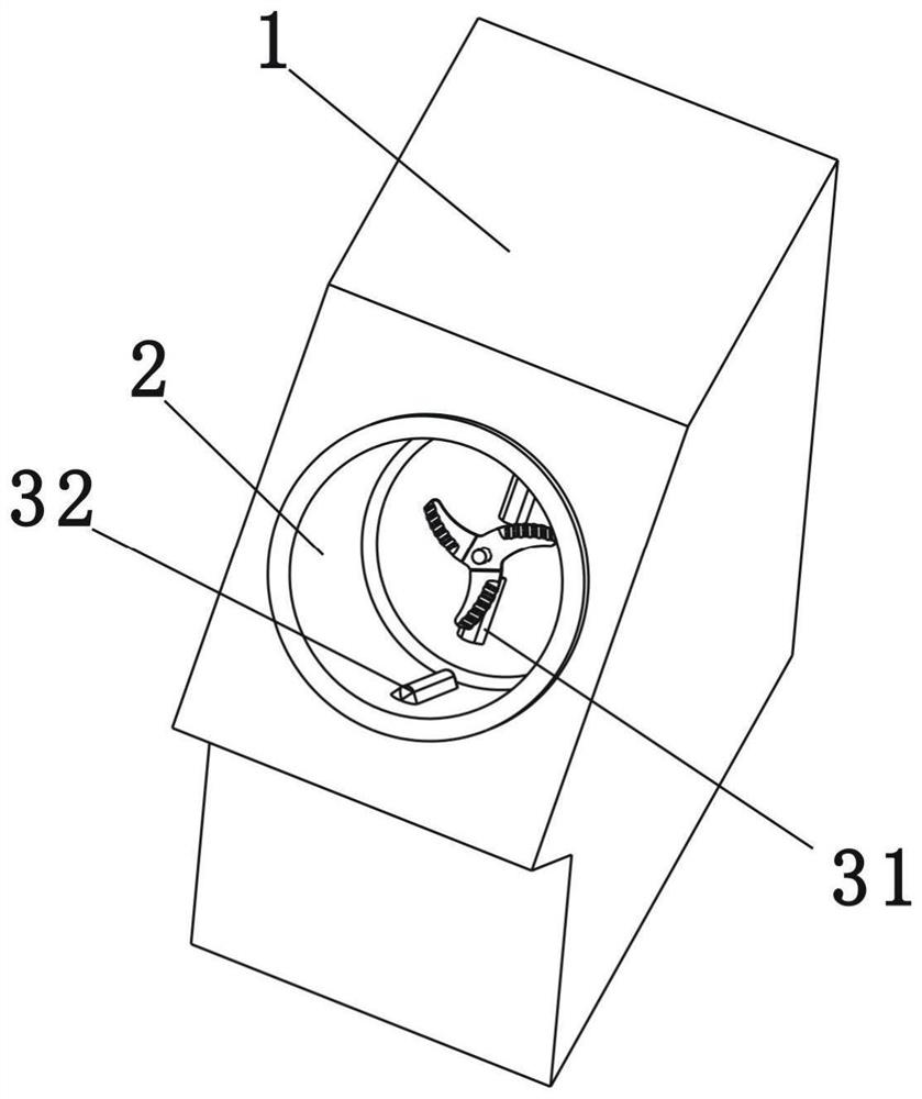
[0032] Such as figure 1 , figure 2 Shown is a schematic structural diagram of the first embodiment of the present invention. A food processor comprising:

[0033] body 1;

[0034] A crushing cup 2, the crushing cup 2 is a barrel-shaped structure with a depth greater than the inner diameter, and the crushing cup 2 is obliquely installed in the body 1, and the inner wall of the crushing cup 2 is provided with an inwardly protruding spoiler rib 3;

[0035] The motor 4 is located outside the crushing cup 2, and the rotating shaft 41 driven by the motor 4 penetrates the cup wall of the crushing cup 2 and extends into the crushing cup 2;

[0036] The crushing blade 5 is located in the crushing cup 2 and is mounted on the end of the rotating shaft 41;

[0037] The peripheral wall of the crushing cup 2 is connected to the bottom through a transition part 21. In this embodiment, the transition part 21 is a rounded corner. After the crushing cup 2 is tilted, the highest point of th...

Embodiment 2

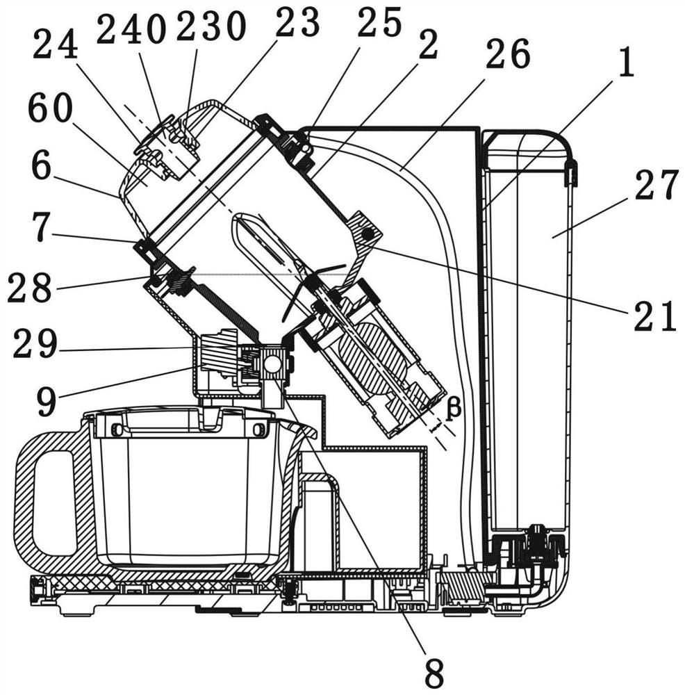
[0046] Such as image 3 Shown is a schematic structural diagram of the second embodiment of the present invention. The difference between this embodiment and the first embodiment is that in this embodiment, a sealing member 7 is installed between the cup cover 6 and the cup mouth, and the sealing member 7 is clamped and fixed by the cup cover 6 and the cup mouth, so as to realize the alignment of the cup. Mouth seal.

[0047] At the same time, in this embodiment, the cup cover 6 has an upwardly recessed auxiliary cavity 60, and the inner surface of the cup cover 6 is provided with a flow blocking portion 23 protruding into the crushing cup 2, and the flow blocking portion 23 is provided with a There is an installation hole 230 that runs through the top wall of the cup cover 6, and a vent plug 24 is installed at the installation hole 230, wherein the vent plug 24 is provided with a vent channel 240 that communicates the space in the crushing cup 2 with the atmosphere. And, th...


PUM


Abstract

The invention relates to kitchen cooking electric appliances, in particular to an automatic food processor. The food processor is characterized by comprising a machine body, a crushing cup, a motor and a crushing blade, wherein the crushing cup is of a barrel-shaped structure, the crushing cup is obliquely installed in the machine body, and a turbulent flow rib protruding inwards is arranged on the inner wall of the crushing cup; the motor is located on the outer side of the crushing cup, and a rotating shaft driven by the motor penetrates the cup wall of the crushing cup and extends into thecrushing cup; and the crushing blade is positioned in the crushing cup and is mounted at the tail end of the rotating shaft, the peripheral wall and the bottom of the crushing cup are connected through a transition part, after the crushing cup is inclined, a connecting line from the highest point of the transition part to the lowest point of a cup opening is L, and a transverse plane where L is located is M, wherein the turbulent flow rib is at least arranged on the part, below the plane M, of the inner wall of the crushing cup. The food processor has no excessive requirements on a rotating speed of the motor, the crushing efficiency can be further improved to a filter-free level, and in addition, operations of automatic cleaning, automatic liquid discharging and the like can be performed.

Description

technical field [0001] The invention relates to kitchen cooking appliances, in particular to an automatic food processing machine. Background technique [0002] The applicant has previously applied for a utility model patent with the patent number "CN201420311715.4" and the title "a soybean milk maker". The patent discloses that the center line of rotation of the inner side wall of the crushing cup is inclined relative to the vertical plane, and the angle of inclination with the vertical plane is 5°-45°. After this setting, the turbulent ribs in the cup can be replaced by tilting the crushing cup. Since there is no grille in the crushing cup, and the inner wall is smooth without spoilers, compared with soybean milk machines with grilles and cups with ribs In other words, on the basis of achieving the same crushing effect, the soymilk machine can be realized without the problem of cleaning dead ends, and the user can manually clean it after use, which is very convenient. Bu...

Claims


Application Information

Patent Timeline
IPC IPC(8): A47J43/07A47J43/08A47J43/046
CPCA47J43/046A47J43/0716A47J43/0722A47J43/085
Inventor 王旭宁张文凡
Owner JOYOUNG CO LTD
Learn More