Wireless bus communication method based on backscattering

A technology of backscattering and bus communication, applied in the direction of transmission modification based on link quality, bus network, adjustment of transmission mode, etc., can solve the problem of high power consumption and achieve the effect of reducing communication power consumption

Active Publication Date: 2020-12-04
UNIV OF ELECTRONIC SCI & TECH OF CHINA
View PDF15 Cites 2 Cited by
  • Summary
  • Abstract
  • Description
  • Claims
  • Application Information

AI Technical Summary

Problems solved by technology

[0003] The purpose of the present invention is to provide a wireless bus communication method based on backscattering to solve the problem of high power consumption in the current traditional backscattering technology

Method used


Image

  • Wireless bus communication method based on backscattering

Examples


Embodiment

[0018] Generally speaking, a standard computer bus may include an SPI bus and an IIC bus, etc. In this embodiment, the SPI bus is used as an example for illustration.

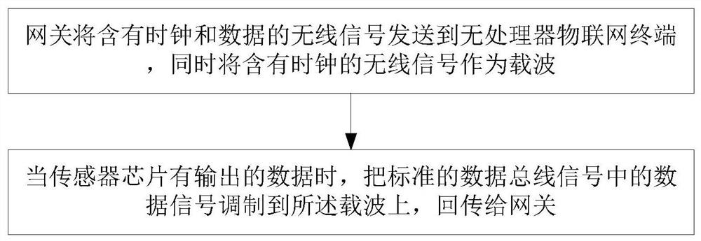
[0019] The backscattering method proposed in this embodiment is essentially a communication method that does not actively generate electromagnetic waves. It is different from the traditional backscattering that is aimed at the baseband signal that has been coded and modulated. This method directly targets the bus signal. to scatter. The problem that needs to be solved for the backscattering of the bus signal is: the bus signal is two signals containing clock and data, but the backscattering is to reflect one baseband signal, that is to say, the backscattering of one line needs to transmit two lines of signals. bus signal.

[0020] In order to solve this problem, the strategy adopted in this embodiment is to directly transmit the bus data by backscattering, and the bus clock is modulated into the wireless signa...


PUM


Abstract

The invention discloses a wireless bus communication method based on backscattering, and belongs to the field of backscattering. The method comprises the steps that a gateway sends a wireless signal containing a clock and data to a processor-free Internet of Things terminal, meanwhile, the wireless signal containing the clock serves as a carrier wave, and when a sensor chip has output data, a datasignal in a standard data bus signal is modulated to the carrier wave and transmitted back to the gateway. A traditional computer bus signal is converted into a wireless signal through a passive backscatter communication technology, and the terminal does not need to generate a high-frequency carrier for wireless communication, so that the communication power consumption is reduced; moreover, thedata and the clock of the computer bus signal can be simultaneously transmitted through one path of wireless signal, and the gateway can be directly recovered into a digital bus signal after receivingthe wireless signal, so that the direct intercommunication of the computer bus signal and the wireless signal without the participation and control of a processor is realized in the uplink communication direction.

Description

technical field [0001] The invention relates to the field of backscattering, in particular to a wireless bus communication method based on backscattering. Background technique [0002] In the current general architecture of IoT terminals, the terminal contains three necessary modules - wireless communication module, sensing module and processor. The wireless communication module is responsible for wireless data exchange with the IoT gateway; the sensor chipset is used to perceive the physical environment; the processor is located between the wireless communication module and the sensor, and implements control and intermediate data processing for both. Among them, the frequency of use of the sensor is usually low, and the typical power consumption is generally only at the microwatt level. In contrast, wireless communication and processors account for the vast majority of terminal energy consumption, with typical power consumption at the milliwatt level. In recent years, wit...

Claims


Application Information

Patent Timeline
IPC IPC(8): H04L12/40H04L27/12H04L1/00
CPCH04L1/0006H04L12/40013H04L27/122
Inventor 鲁力李松璠张翀宋一杭郑辉刘璐
Owner UNIV OF ELECTRONIC SCI & TECH OF CHINA
Why Eureka
Try Eureka