Encoder combination switch
A combined switch and encoder technology, applied in the direction of electric switches, electrical components, circuits, etc., can solve the problems of troublesome line connection, inconvenient operation, large instrument panel area, etc., and achieve convenient line connection, small space occupation, and easy operation Effect
- Summary
- Abstract
- Description
- Claims
- Application Information
AI Technical Summary
Problems solved by technology
Method used
Image

Examples
Embodiment Construction
[0015] The present invention will be further described in detail below in conjunction with the accompanying drawings and embodiments.
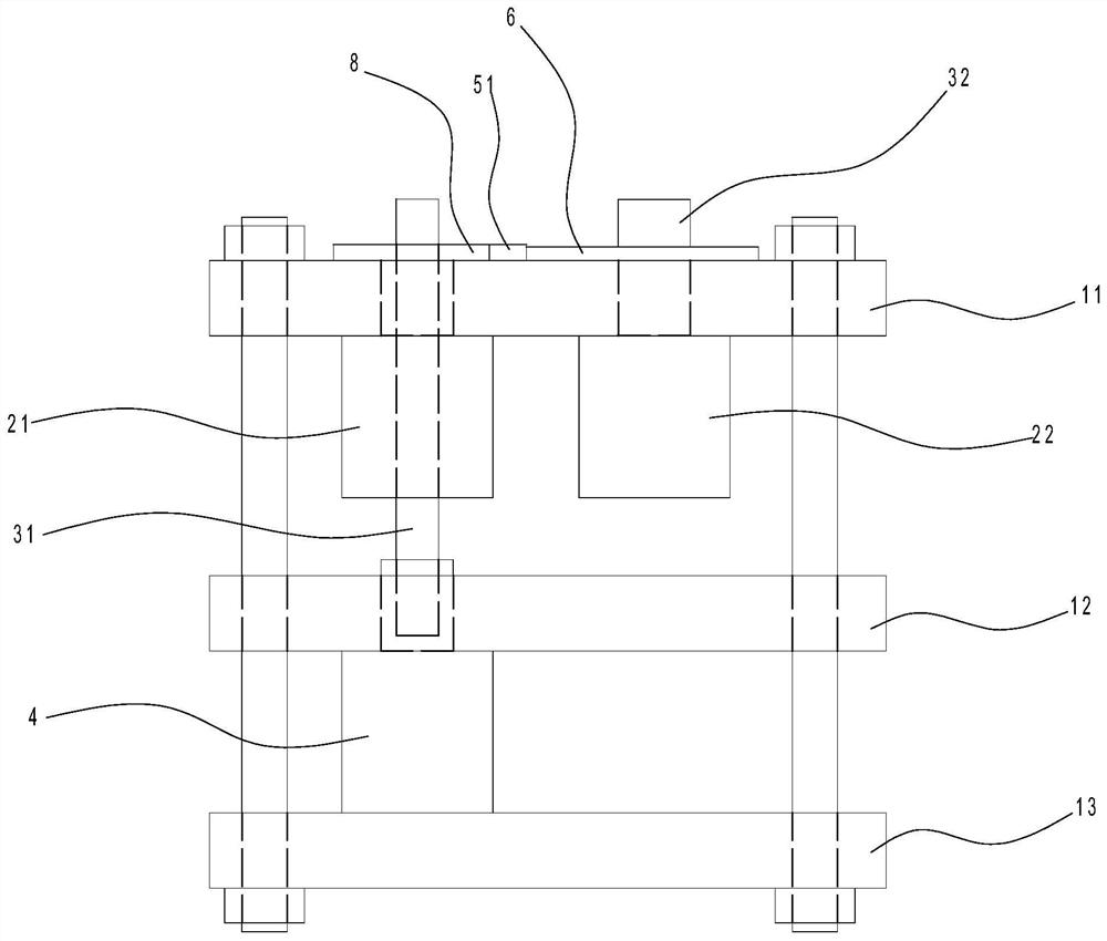
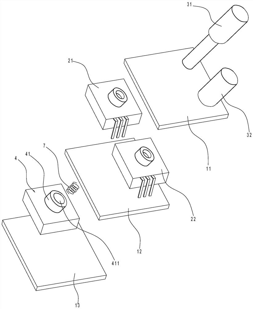
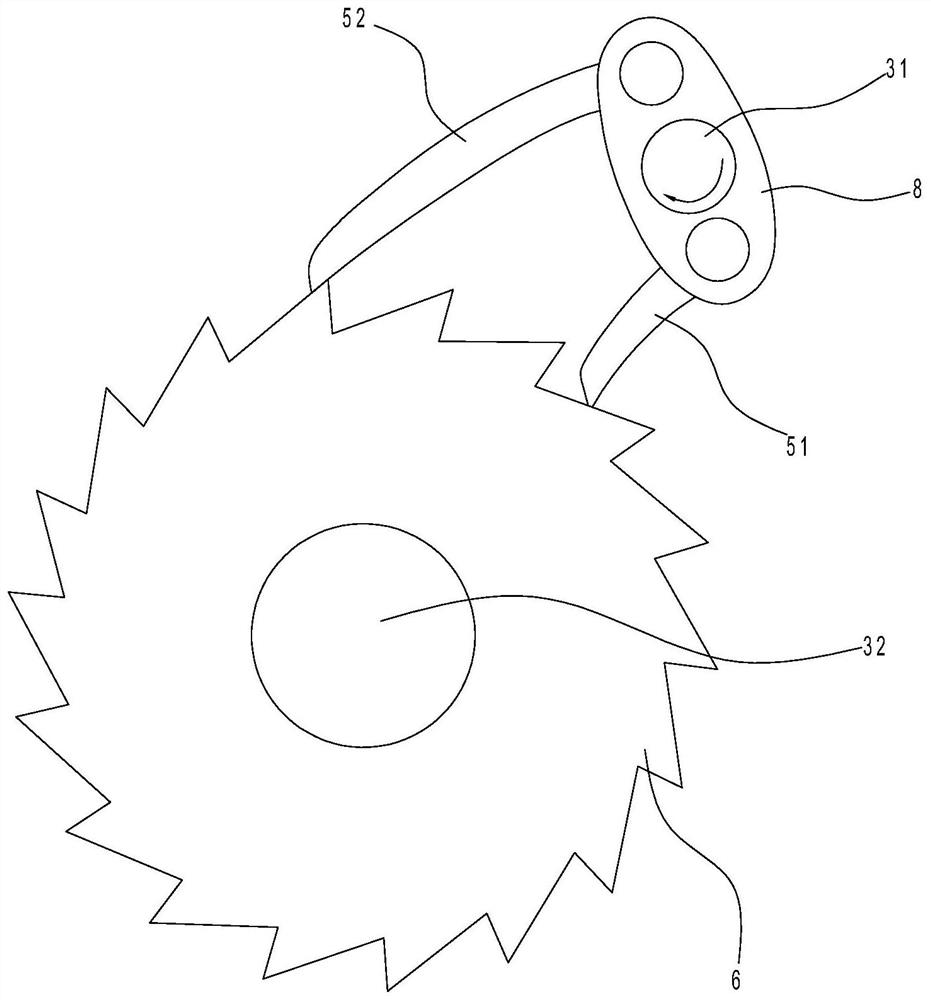
[0016] Such as Figures 1 to 4 As shown, the embodiment of the present invention discloses an encoder combination switch, including an upper cover plate 11, a middle cover plate 12, a lower cover plate 13, a first encoder 21, a second encoder 22, a potentiometer 4, a short spine Claw 51, long ratchet 52, ratchet 6, spring 7 and rotating rod 8.
[0017] 1. Among them, the first encoder 21 and the second encoder 22 are arranged side by side between the upper cover 11 and the middle cover 12, and the potentiometer 4 is arranged between the middle cover 12 and the lower cover 13. A first control shaft 31 is arranged between the encoder 21 and the potentiometer 4, the first control shaft 31 is connected through the knob 41 of the first encoder 21 and the potentiometer 4, and the second control shaft 31 is provided on the second encoder 22. Shaft ...
PUM
 Abstract
Description
Claims
Application Information
 - Generate Ideas
- Intellectual Property
- Life Sciences
- Materials
- Tech Scout
- Unparalleled Data Quality
- Higher Quality Content
- 60% Fewer Hallucinations
Browse by: Latest US Patents, China's latest patents, Technical Efficacy Thesaurus, Application Domain, Technology Topic, Popular Technical Reports.
© 2025 PatSnap. All rights reserved.Legal|Privacy policy|Modern Slavery Act Transparency Statement|Sitemap|About US| Contact US: help@patsnap.com