
Three-encoder combination switch

A combination switch and encoder technology, applied in the direction of electric switches, electrical components, circuits, etc., can solve the problems of large instrument panel area, constraints on the miniaturization and portability of measurement and control instruments, and complicated line connections

Inactive Publication Date: 2020-12-04
黄伟岳
View PDF1 Cites 0 Cited by
  • Summary
  • Abstract
  • Description
  • Claims
  • Application Information

AI Technical Summary

Problems solved by technology

However, in the process of use, especially when the instrument panel of the measurement and control instrument is small or the internal assembly space is insufficient, the disadvantages of traditional encoders and single-layer encoders are obvious: 1. Occupies a large area of ​​the instrument panel, and both components require Larger surface area of ​​the panel; 2. The operation function is single, and each knob can only achieve a single function, which often cannot realize the expected function well; 3. The operation is inconvenient, and the two knobs require multiple operations; 4. The wiring connection is troublesome, and the two The position of each component affects the connection line, resulting in the complexity of line connection
Therefore, the traditional method of use also requires the measurement and control instrument to provide sufficient plane size, thus restricting the miniaturization and portability of the measurement and control instrument

Method used


Image

  • Three-encoder combination switch
  • Three-encoder combination switch
  • Three-encoder combination switch

Examples


Embodiment Construction

[0014] The present invention will be further described in detail below in conjunction with the accompanying drawings and embodiments.

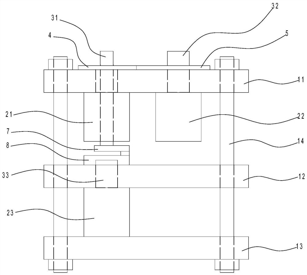
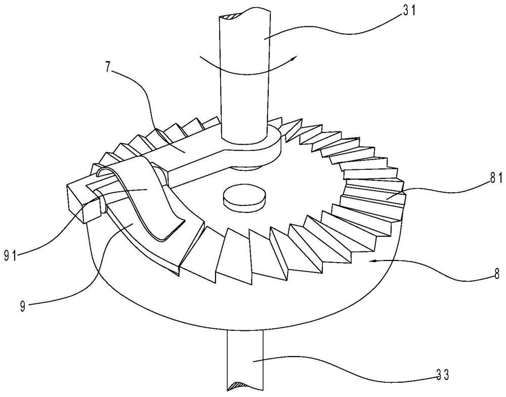
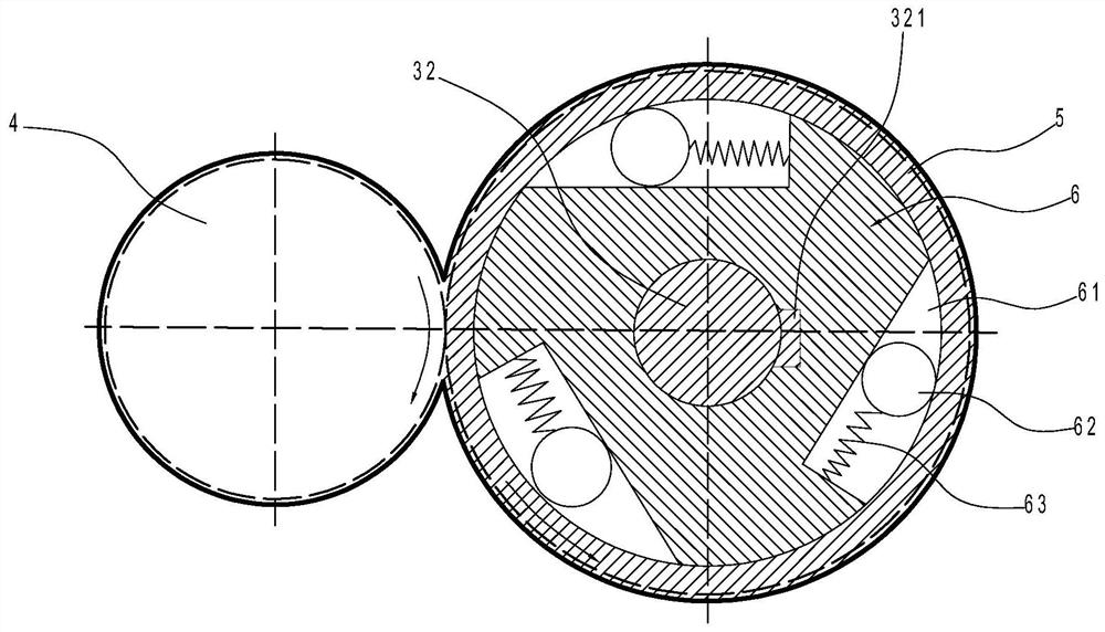
[0015] Such as Figures 1 to 3 As shown, the embodiment of the present invention discloses a three-encoder combination switch, including an upper cover 11, a middle cover 12, a lower cover 13, a first encoder 21, a second encoder 22, and a third encoder 23 , the first control shaft 31, the second control shaft 32, the third control shaft 33, the driving gear 4, the ring gear 5, the turntable 6, the steel ball 62, the spring 63, the rotating rod 7, the push piece 9, the toothed plate 8 and the shrapnel 91.

[0016] Wherein, the first encoder 21 and the second encoder 22 are arranged in parallel between the upper cover 11 and the middle cover 12, the third encoder 31 is arranged between the middle cover 12 and the lower cover 13, and the first encoder The device 21 is provided with a first control shaft 31 protruding from the upper and lower e...


PUM


Abstract

The invention discloses a three-encoder combination switch which is characterized by comprising a first encoder, a second encoder and a third encoder, a first control shaft is arranged on the first encoder, a second control shaft is arranged on the second encoder, a third control shaft is arranged on the third encoder, a driving gear is arranged at the upper extending end of the first control shaft, the driving gear is engaged with a gear ring, a rotary disc in transmission connection with the second control shaft is rotationally arranged in a gear ring, a plurality of cutting grooves are evenly distributed in the peripheral wall of the rotary disc in the circumferential direction, and steel balls and springs are arranged in the cutting grooves; a rotating rod is arranged at the lower extending end of the first control shaft, a push piece is arranged on the rotating rod in a rotating mode, a fluted disc is arranged at the extending end of the third control shaft, and an elastic piece for pressing the push piece on the fluted disc is arranged at the outer end of the rotating rod. The three-encoder combination switch provided by the invention has the characteristics of small occupiedspace, combined functions, simplicity in operation and convenience in circuit connection.

Description

technical field [0001] The invention relates to a combined switch, in particular to a three-encoder combined switch. Background technique [0002] Encoders and single-layer encoders are commonly used electronic components in measurement and control instruments. At present, the two electronic components are used separately and connected to each other through line connections. However, in the process of use, especially when the instrument panel of the measurement and control instrument is small or the internal assembly space is insufficient, the disadvantages of traditional encoders and single-layer encoders are obvious: 1. Occupies a large area of ​​the instrument panel, and both components require Larger panel surface area; 2. The operation function is single, each knob can only achieve a single function, and often cannot achieve the expected function well; 3. Inconvenient operation, two knobs require multiple operations; 4. The wiring connection is troublesome, two The pos...

Claims


Application Information

Patent Timeline
Patent Type & Authority Applications(China)
IPC IPC(8): H01H19/20H01H19/10H01H19/02H01H19/64
CPCH01H19/02H01H19/10H01H19/20H01H19/64
Inventor 黄伟岳
Owner 黄伟岳
Learn More