A box-type transformer device that can automatically remove snow and prevent moisture

A box-type transformer, automatic technology, applied in the direction of transformer/inductor cooling, transformer/inductor casing, transformer/inductor parts, etc., can solve the problems of transformer equipment damage, internal equipment damage, power supply accidents, etc., to achieve Ensure normal work and avoid damage

Active Publication Date: 2021-05-14
江苏智慧工场技术研究院有限公司
View PDF8 Cites 0 Cited by
  • Summary
  • Abstract
  • Description
  • Claims
  • Application Information

AI Technical Summary

Problems solved by technology

[0002] At present, most box-type transformers are installed outdoors, so this type of transformer is more susceptible to the impact of bad weather and the environment. In case of heavy snow, the snow will continue to cover the upper end of the outer box of the transformer, so that the snow will continue to contact the box. If the outer surface is in contact, it will corrode the outer surface of the box and even the melted snow will penetrate into the box, causing irreversible damage to the transformer equipment, and in wet weather, moisture will continue to enter the box-type transformer at this time , thus causing damage to its internal equipment or even power supply accidents

Method used


Image

  • A box-type transformer device that can automatically remove snow and prevent moisture
  • A box-type transformer device that can automatically remove snow and prevent moisture
  • A box-type transformer device that can automatically remove snow and prevent moisture

Examples


Embodiment Construction

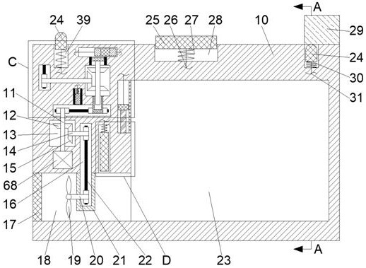
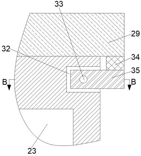
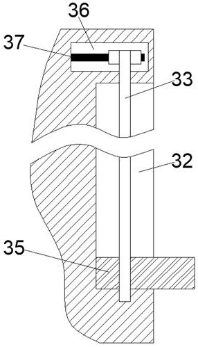
[0018] Combine below Figure 1-5 The present invention is described in detail, wherein, for the convenience of description, the orientations mentioned below are defined as follows: figure 1 The up, down, left, right, front and back directions of the projection relationship itself are the same.

[0019] A box-type transformer device capable of automatic snow removal and moisture-proof described in conjunction with accompanying drawings 1-5 includes a main body box 10, which is provided with a sliding plate chamber 28 with an upward opening. The slider cavity 28 is a trigger slider cavity 39 which is symmetrically arranged in the center and opened upwards. The lower side of the slider cavity 39 is provided with a transformer chamber 23, and the lower end of the left end wall of the transformer chamber 23 is connected to There is a vent 18 opening to the left, the upper end of the left end wall of the transformer equipment chamber 23 communicates with a humidity monitoring chamb...


PUM


Abstract

The invention relates to the related field of power grid monitoring, and discloses a box-type transformer device capable of automatically removing snow and moisture, including a main body box, which is provided with a sliding plate cavity with an upward opening, and the main body box is equipped with a sliding plate cavity that is symmetrically arranged around the center. And the opening of the trigger slider cavity is upward, and the lower side of the trigger slider cavity is provided with a pressure transformation equipment cavity. This device triggers the snow on the upper surface of the device through the snow trigger skateboard to monitor the snow accumulation on the upper surface of the device in real time. To avoid the damage caused by the snow water to the device, to ensure the normal operation of the equipment in the chamber of the pressure transformation equipment, and to monitor the humidity in the chamber of the pressure transformation equipment in real time through synthetic fibers, and to change the position of the vent by blocking the slide plate. Size, and cooperate with the heat generated by the transformer itself to accelerate the evaporation of moisture in the humid air in the cavity of the transformer, and finally exhaust it to the outside through the exhaust fan, so as to achieve the purpose of moisture resistance.

Description

technical field [0001] The invention relates to the related field of power grid monitoring, in particular to a box-type transformer device capable of automatic snow removal and moisture resistance. Background technique [0002] At present, most box-type transformers are installed outdoors, so this type of transformer is more susceptible to the impact of bad weather and the environment. In case of heavy snow, the snow will continue to cover the upper end of the outer box of the transformer, so that the snow will continue to contact the box. If the outer surface is in contact, it will corrode the outer surface of the box and even the melted snow will penetrate into the box, thereby causing irreversible damage to the transformer equipment, and in wet weather, moisture will continue to enter the box-type transformer at this time , thus causing damage to its internal equipment or even power supply accidents. Contents of the invention [0003] The object of the present inventio...

Claims


Application Information

Patent Timeline
Patent Type & Authority Patents(China)
IPC IPC(8): H01F27/40H01F27/08H01F27/02B01D53/26B08B1/00
CPCB01D53/26B08B1/008H01F27/022H01F27/08H01F27/40H01F27/402
Inventor 李杰
Owner 江苏智慧工场技术研究院有限公司
Why Eureka
Try Eureka