Detection processing equipment with automatic positioning function for circular bridge electronic element

A technology for electronic components and processing equipment, applied in the field of testing and processing equipment, can solve the problems of reducing production quality, prone to errors in quality management, and small size.

Inactive Publication Date: 2020-12-04
东莞市固德智能科技有限公司
View PDF0 Cites 2 Cited by
  • Summary
  • Abstract
  • Description
  • Claims
  • Application Information

AI Technical Summary

Problems solved by technology

[0004] Aiming at the deficiencies of the prior art, the present invention provides a detection and processing equipment with automatic positioning of the round bridge electronic components, which solves the problem that most of the electronic components proposed in the above background technology are manually placed on the round bridge electronic components after the production is completed. Detection, most of the detection methods use direct visual and hands-on testing for firmness or use inspection instruments to test the round bridge electronic components one by one, and then classify the round bridge electronic components through observation, so that due to the small size of the round bridge electronic components Therefore, it is time-consuming and labor-intensive in the inspection process, and there are unstable factors in manual participation. Quality management is prone to mistakes, resulting in problems such as lowering production quality.

Method used


Image

  • Detection processing equipment with automatic positioning function for circular bridge electronic element
  • Detection processing equipment with automatic positioning function for circular bridge electronic element
  • Detection processing equipment with automatic positioning function for circular bridge electronic element

Examples


Embodiment Construction

[0028] The following will clearly and completely describe the technical solutions in the embodiments of the present invention with reference to the accompanying drawings in the embodiments of the present invention. Obviously, the described embodiments are only some, not all, embodiments of the present invention.

[0029]In the description of the present invention, unless otherwise stated, the meaning of "plurality" is two or more; the terms "upper", "lower", "left", "right", "inner", "outer" , "front end", "rear end", "head", "tail", etc. indicate the orientation or positional relationship based on the orientation or positional relationship shown in the drawings, and are only for the convenience of describing the present invention and simplifying the description, rather than Indicates or implies that the device or element referred to must have a particular orientation, be constructed and operate in a particular orientation, and therefore should not be construed as limiting the ...


PUM


Abstract

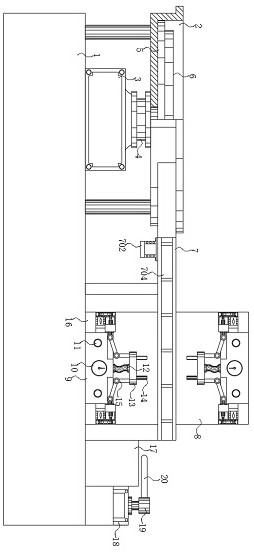
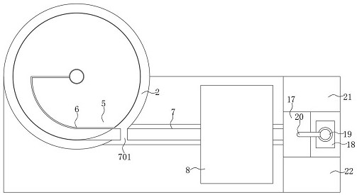
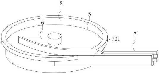
The invention discloses detection processing equipment with an automatic positioning function for a circular bridge electronic element, which comprises a bottom case, A feeding mechanism is arranged on the upper surface of the left side of the bottom case, a transmission mechanism is connected to the right side surface of the feeding mechanism, and the right end of the transmission mechanism is arranged at the center line position of a support frame in a transverse crossing mode; a flow dividing table is installed on the right side of the support frame; and a certified product bin and a defective product bin are symmetrically arranged on the two sides of the flow dividing table correspondingly. A detector and a support plate are arranged at the bottom and the upper portion of the support frame in a mirror symmetry mode. As the support plate is arranged, a detection sleeve can be conveniently positioned and supported, so that the detection sleeve can be matched with the support legs ofthe circular bridge electronic element in position, and the lifting mechanism and the support plate are connected through the connecting rod, so that the support plate can be conveniently driven to ascend or descend, and the detection sleeve and the circular bridge electronic element can be in a closed state; and the signals are transmitted to the detector through a connecting wire.

Description

technical field [0001] The invention relates to the technical field of detection and processing, in particular to a detection and processing equipment with automatic positioning of round bridge electronic components. Background technique [0002] The history of the development of electronic components is actually a condensed history of electronic development. Electronic technology is an emerging technology developed at the end of the nineteenth century and the beginning of the twentieth century. It developed the fastest and was most widely used in the twentieth century. An important sign, electronic components are components of electronic components and small machines and instruments. They are often composed of several parts and can be used in similar products; they often refer to certain parts in industries such as electrical appliances, radios, and instruments. The general term for electronic devices such as capacitors, transistors, hairsprings, and springs. Common ones in...

Claims


Application Information

Patent Timeline
Patent Type & Authority Applications(China)
IPC IPC(8): G01R31/00
CPCG01R31/00
Inventor 范裕鹏钟锦洪余兆荣
Owner 东莞市固德智能科技有限公司
Why Eureka
Try Eureka