
Pressure transmitter convenient to disassemble and assemble

A transmitter and pressure technology, applied in the direction of measuring fluid pressure, instruments, measuring devices, etc., can solve the problems of general sealing effect, inconvenient disassembly, corrosion, etc., and achieve the effect of easy detection of pipelines, good sealing effect, and avoiding rust prevention

Inactive Publication Date: 2020-12-04
XIAN LANXIN IND AUTOMATION ENG CO LTD
View PDF1 Cites 0 Cited by
  • Summary
  • Abstract
  • Description
  • Claims
  • Application Information

AI Technical Summary

Problems solved by technology

[0003] According to the installation structure of a pressure transmitter with the Chinese patent number CN209085829U, when in use, first put a rubber ring on the side wall of the installation rod, then hold the fixed ring with a wrench, and connect the installation rod and the pipe thread on the Together, the first locking block and the second locking block clamp the fixed ring and the pipe together. When clamping, first insert the first protrusion into the first groove, and insert the second protrusion into the second groove. At this time, the sealing protrusion is inserted into the sealing groove, and the two connecting blocks are connected together by the locking bolt, and the line is passed through the threading hole on the rubber plug through the line joint, and screwed to the line interface, the installation and fixing can be completed , the sealing effect of this connection method is average, and the set locking bolts will also cause moisture and corrosion, and it is also inconvenient to disassemble later

Method used


Image

  • Pressure transmitter convenient to disassemble and assemble
  • Pressure transmitter convenient to disassemble and assemble

Examples


Embodiment 1

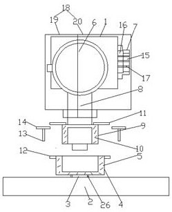
[0022] Example 1 as Figure 1-2 As shown, a pressure transmitter that is easy to assemble and disassemble according to an embodiment of the present invention includes a pressure transmitter body 1 and a pipe 2, and the top end of the pipe 2 is provided with a welded connecting pipe 3, and the connecting pipe 3 The inside communicates with the inside of the pressure transmitter body 1, the outer wall of the connecting pipe 3 is fixed with a hollow first fixed sleeve 4, the top of the first fixed sleeve 4 is an open end, and the first fixed sleeve 4 The inner wall is fixed with a first sealing rubber ring 5, the side wall of the pressure transmitter body 1 is respectively provided with an instrument panel 6 and a line joint 7, and the lower end side wall of the pressure transmitter body 1 is fixedly connected with a mounting Rod 8, the side wall of the installation rod 8 is provided with a through hole, the through hole communicates with the pressure transmitter body 1, and the ...

Embodiment 2

[0023] Embodiment 2 is on the basis of embodiment 1 such as figure 1 As shown, for the line connector 7, the side wall of the line connector 7 is provided with a line interface 15, and the line interface 15 is filled with a rubber plug 16, and the side wall of the rubber plug 16 is in contact with the The inner wall of the line interface 15 is slidably connected, the inner wall of the line interface 15 is provided with threads, and the side wall of the rubber plug 16 is provided with a plurality of threading holes 17 at equal intervals.

[0024] Through the above-mentioned scheme of the present invention, the beneficial effect is: through the line joint 7, the wire is passed through the threading hole 17 on the rubber plug 16, and is screwed on the line joint 7, which not only improves the sealing performance, but also effectively protects the line and avoids The wiring is damaged.

Embodiment 3

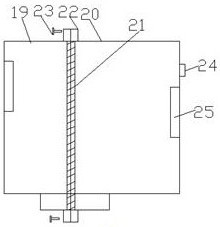
[0025] Embodiment 3 is such as on the basis of embodiment 1 Figure 1-2 As shown, for the pressure transmitter body 1, the pressure transmitter body 1 is covered with a plastic protective cover 18, and the pressure transmitter body 1 is divided into a left protective cover 19 and a right protective cover 20, The left protective cover 19 and the right protective cover 20 are spliced ​​together, and the bottoms of the left protective cover 19 and the right protective cover 20 are respectively sleeved on the installation rod 8, and the left protective cover 19 and the right protective cover 20 Sealing strips 21 are fixed at the joints, and a mounting plate 22 is fixed on the left protective cover 19 and the right protective cover 20 , and a secondary plastic screw 23 is screwed on the mounting plate 22 .

[0026] Through the above scheme of the present invention, the beneficial effect is that the plastic protective cover 18 wraps the pressure transmitter body 1, so it plays a goo...


PUM


Abstract

The pressure transmitter convenient to disassemble and assemble comprises a pressure transmitter body and a pipeline; the top end of the pipeline is provided with a connecting pipe which is welded tothe pipeline integrally; the interior of the connecting pipe is communicated with the interior of the pressure transmitter body; and the outer wall of the connecting pipe is fixedly sleeved with a hollow first fixing sleeve; the top end of the first fixing sleeve is an open end; a first sealing rubber ring is fixedly arranged on the inner wall of the first fixing sleeve; and an instrument panel and a line connector are arranged on the side wall of the pressure transmitter body. According to the pressure transmitter convenient to disassemble and assemble, the arranged first sealing rubber ringwraps the second fixing sleeve of the connecting pipe, so that secondary sealing installation is achieved; after installation, an installation sheet arranged on the first sealing rubber ring corresponds to an auxiliary installation sheet arranged on the second sealing rubber ring, then plastic threaded rods are spirally inserted into the installation sheet and the auxiliary installation sheet, andfinal fixing is conducted; the plastic threaded rods can be prevented from being rusted, the inconvenience of later disassembly is avoided, and the sealing effect is good during installation.

Description

technical field [0001] The invention relates to the field of pressure transmitters, in particular to a pressure transmitter that is easy to assemble and disassemble. Background technique [0002] A pressure transmitter is a device that converts pressure into a pneumatic signal or an electric signal for control and remote transmission. It can convert physical pressure parameters such as gas and liquid felt by the load cell sensor into a standard electrical signal for supply Indicating alarms, recorders, regulators and other secondary instruments for measurement, indication and process adjustment, are widely used in various industrial automatic control environments. Existing pressure transmitters are generally installed with threads. Once the rainwater infiltrates and gets damp, the threads will be corroded, so it is very inconvenient to disassemble the pressure transmitter. [0003] According to the installation structure of a pressure transmitter with the Chinese patent n...

Claims


Application Information

Patent Timeline
Patent Type & Authority Applications(China)
IPC IPC(8): G01L19/14
CPCG01L19/143G01L19/144G01L19/147
Inventor 王岚
Owner XIAN LANXIN IND AUTOMATION ENG CO LTD
Learn More