Visual transparent disintegrating slag drainer

A slag drainer, transparent technology, applied in the field of transparent slag drainer, can solve the problems of poor sanitation inside the drainer, low installation quality, difficult operation, etc., and achieve the effect of easy cleaning and easy assembly and disassembly

Inactive Publication Date: 2020-12-04
FOSHAN ZAL ELECTRICAL TECH CO LTD
View PDF0 Cites 0 Cited by
  • Summary
  • Abstract
  • Description
  • Claims
  • Application Information

AI Technical Summary

Problems solved by technology

[0002] The drainer is a tool installed at the mouth of the sink to prevent food residues, garbage, etc. Some drains can collect kitchen waste, etc., but they need to be cleaned manually. It is easy to get dirty hands and make germs and bacteria adhere to the hands. If the drain is not cleaned for a long time, the kitchen waste will still rot gradually. It emits a foul smell, so it needs to be cleaned frequently, and although the existing kitchen waste disposer is installed at the bottom of the sink, it can also clean up the garbage, but the existing kitchen waste disposer needs to be drilled into the cabinet for installation, which is difficult to operate , leading to poor installation quality, water leakage, machine falling off, etc. The existing drains have the disadvantages of difficult assembly and disassembly, and the traditional drains are not visualized, and it is impossible to judge whether the interior is blocked and where the blockage is. There are a lot of obstacles during the maintenance, and because it is not visualized, it is impossible to judge the sanitation inside the drain, and it cannot be dealt with in time, resulting in extremely poor sanitation inside the drain after a long time, and a large number of bacteria

Method used


Image

  • Visual transparent disintegrating slag drainer
  • Visual transparent disintegrating slag drainer
  • Visual transparent disintegrating slag drainer

Examples


Embodiment Construction

[0023] The present invention will be further described below in conjunction with accompanying drawing description and specific embodiment:

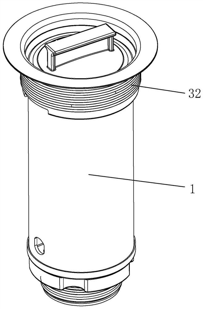
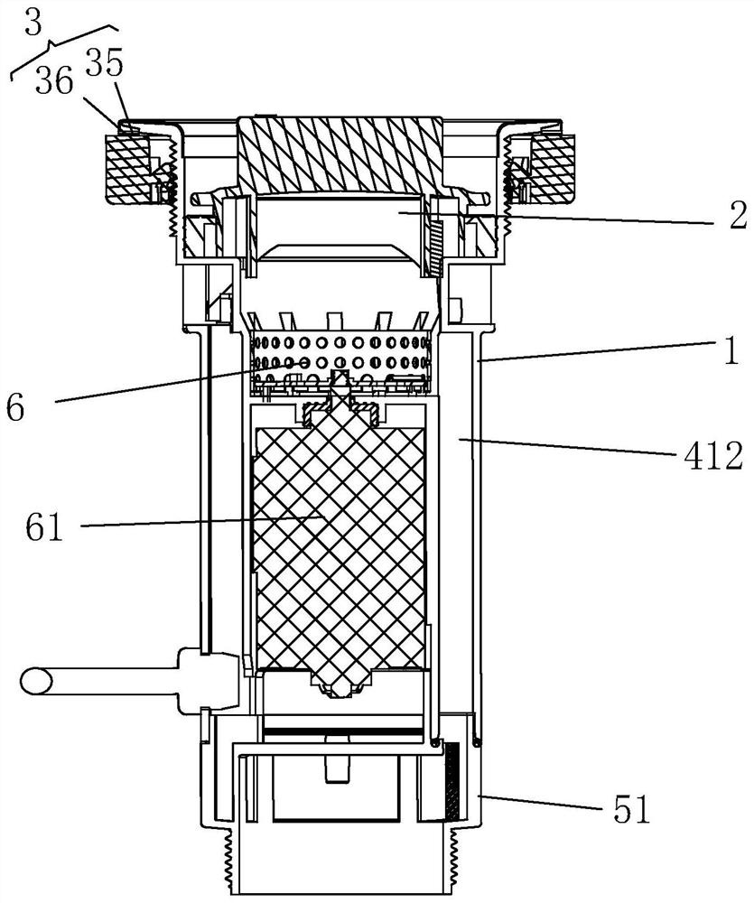
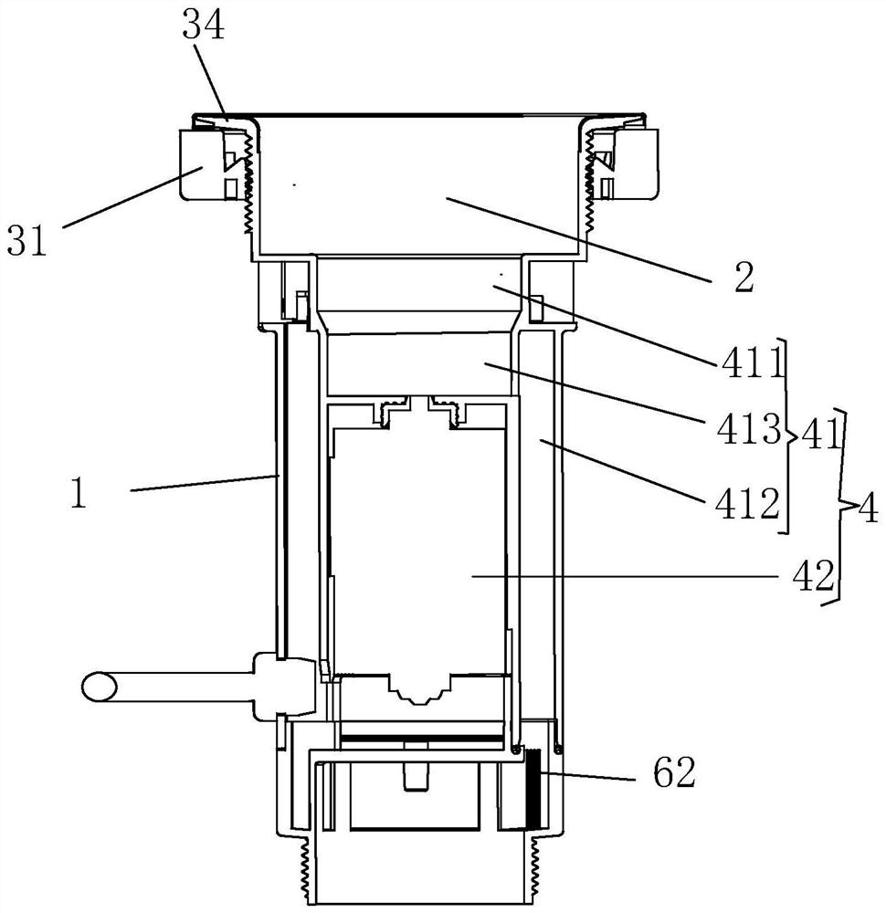
[0024] Such as Figures 1 to 5 A visualized transparent slag drainer as shown includes a flange main body 1, a water hole 2 is provided at the center of the flange main body 1, and a flange that enables the The connecting structure 3 connecting the main body 1 with the notch of the water tank is provided with a water and electricity separation chamber 4 inside the flange main body 1, and a cutter 6 and a motor 61 for driving the cutter 6 are arranged in the water and electricity separation chamber. The bottom of the flange main body 1 is provided with a water connection 5, and a deodorization and sterilization module 62 is arranged in the water connection 5. The flange main body 1, the water and electricity separation chamber 4, and the water connection 5 are visualized. The connection structure can be placed at the mouth of the water ta...


PUM


Abstract

The invention discloses a visual transparent disintegrating slag drainer. The visual transparent disintegrating slag drainer comprises a flange main body, wherein a water through hole is formed in thecenter of the flange main body; a connecting structure capable of connecting the flange main body with a notch of a water tank is arranged on the flange main body; a water-electricity separation cavity is formed in the flange main body; a cutter and a motor for driving the cutter to move are arranged in the water-electricity separation cavity; a draining joint is arranged at the bottom of the flange main body; a deodorizing and sterilizing module is arranged in the draining joint; and the flange main body, the water-electricity separation cavity and the draining joint are subjected to visualtreatment. The visual transparent disintegrating slag drainer is easy and convenient to assemble and disassemble, and can directly replace the conventional drainer; a kitchen draining structure and anadditional connecting pipe are not required to be changed; the whole machine is directly put from the upper end of the notch of the water tank, and the phenomena of low mounting quality, water leakage, machine falling and the like caused by difficult operation due to drilling into a cabinet for mounting like the conventional kitchen garbage processor are avoided; and the drainer or a sewer is cleaned more favorably.

Description

technical field [0001] The invention relates to the field of living equipment, in particular to a visualized transparent slag drainer. Background technique [0002] The drainer is a tool installed at the mouth of the sink to prevent food residues, garbage, etc. Some drains can collect kitchen waste, etc., but they need to be cleaned manually. It is easy to get dirty hands and make germs and bacteria adhere to the hands. If the drain is not cleaned for a long time, the kitchen waste will still rot gradually. It emits a foul smell, so it needs to be cleaned frequently, and although the existing kitchen waste disposer is installed at the bottom of the sink, it can also clean up the garbage, but the existing kitchen waste disposer needs to be drilled into the cabinet for installation, which is difficult to operate , leading to poor installation quality, water leakage, machine falling off, etc. The existing drains have the disadvantages of difficult assembly and disassembly, and...

Claims


Application Information

Patent Timeline
Patent Type & Authority Applications(China)
IPC IPC(8): E03C1/22E03C1/266
CPCE03C1/22E03C1/266E03C1/2665
Inventor 陈国海常亮钟惠文陈毅昌
Owner FOSHAN ZAL ELECTRICAL TECH CO LTD
Why Eureka
Try Eureka