
Self-adaptive carrying clamp for aluminum foil coil

An adaptive, aluminum foil roll technology, applied in transportation and packaging, cleaning methods and utensils, and pollution prevention methods, etc., can solve the problems of low handling efficiency and poor adaptability of aluminum foil rolls, and achieve improved sliding stability, high efficiency and stability clamping effect

Pending Publication Date: 2020-12-04
SHANGHAI SONGSHENG ROBOT SYST CO LTD
View PDF0 Cites 0 Cited by
  • Summary
  • Abstract
  • Description
  • Claims
  • Application Information

AI Technical Summary

Problems solved by technology

[0003] In the aluminum foil production process, the aluminum foil roll needs to be transported, so the corresponding handling fixture will be used. However, the current fixture clamps from all sides, which has poor adaptability to the aluminum foil roll, resulting in low handling efficiency, so it needs to be optimized.

Method used


Image

  • Self-adaptive carrying clamp for aluminum foil coil
  • Self-adaptive carrying clamp for aluminum foil coil
  • Self-adaptive carrying clamp for aluminum foil coil

Examples


Embodiment 1

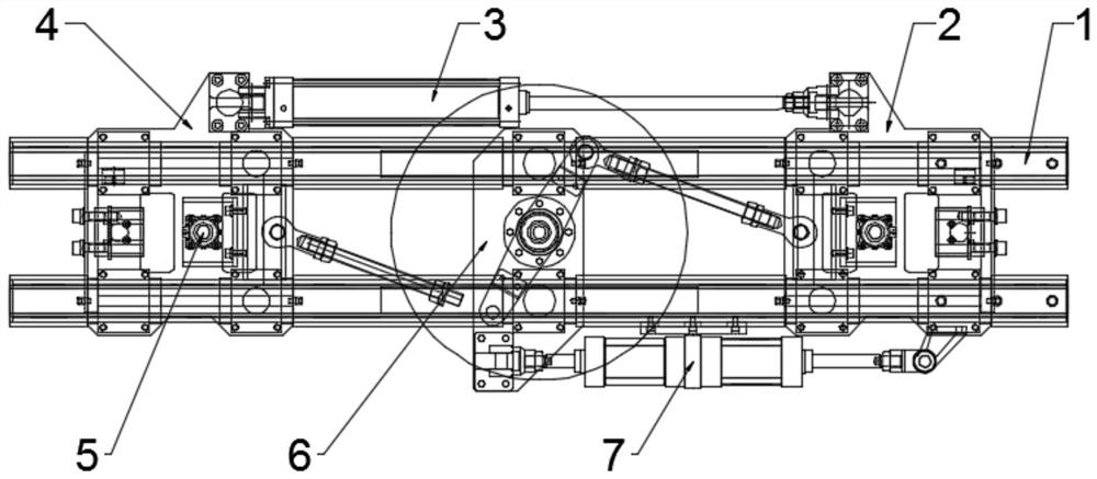
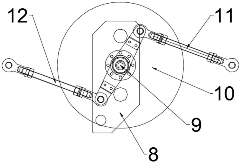
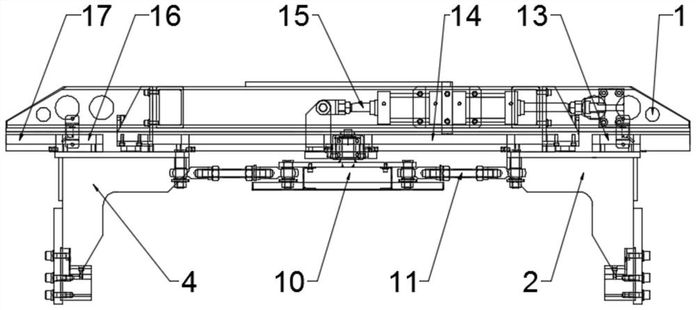
[0022] Such as figure 1 , 2 , The self-adaptive handling fixture for aluminum foil rolls shown in 3 includes a guide rail 1, and the guide rail 1 is a linear guide rail, preferably two, to ensure stable operation; the first splint 2 and the second splint that are slidingly connected to it are installed on the guide rail 1 4. The second splint 4 is connected to the first splint 2 through the clamping cylinder 3, and the clamping cylinder 3 is arranged on the side of the guide rail 1, that is, the expansion and contraction of the clamping cylinder 3 brings the first splint 2 and the second splint. The splints 4 are close to or far away from each other; the second splint 4 and the first splint 2 are equipped with a positioning pin 5 that matches the aluminum foil roll, that is, it is fixed by the positioning pin 5 and the roll material hole of the aluminum foil roll. , and then bring the first clamping plate 2 and the second clamping plate 4 close to each other through the clamp...

Embodiment 2

[0027] This embodiment is further optimized on the basis of embodiment 1, as Figure 4 As shown, a bearing 18 is installed inside the fixing plate 8 , and the bearing 18 is sheathed on the outside of the rotating shaft 9 , that is, the rotation stability of the fixing frame 10 is improved by arranging the bearing 18 .

[0028] Further, the first fixed shaft 19 and the third fixed shaft 21 are fixedly installed in the fixed frame 10, the third fixed shaft 21 and the first fixed shaft 19 are arranged symmetrically with respect to the rotating shaft 9, and the first connecting rod 11 One end is sleeved on the outside of the first fixed shaft 19 and connected to it in rotation, and the other end is installed with a second fixed shaft 20 connected to it in rotation. The second fixed shaft 20 is fixedly installed in the first splint 2, and the second connection One end of the rod 12 is sheathed on the outside of the third fixed shaft 21 and is rotatably connected with it, and the ot...


PUM


Abstract

The invention belongs to the technical field of clamps and relates to a self-adaptive carrying clamp for an aluminum foil coil. The self-adaptive carrying clamp comprises a guide rail, a first clamping plate and a second clamping plate are installed on the guide rail, the second clamping plate is connected with the first clamping plate through a clamping air cylinder, the clamping air cylinder isarranged on one side of the guide rail, and positioning plug pins matched with aluminum foil coil are installed on the second clamping plate and the first clamping plate correspondingly. An anti-falling mechanism is installed at the bottom of the guide rail, one end of the anti-falling mechanism is connected with the first clamping plate, the other end of the anti-falling mechanism is connected with the second clamping plate, a floating mechanism is installed on the side, away from the clamping air cylinder, of the guide rail, one end of the floating mechanism is connected with the first clamping plate, and the other end of the floating mechanism is connected with the anti-falling mechanism. By arranging the clamping air cylinder to be matched with the anti-falling mechanism and the floating mechanism, efficient and stable clamping of an aluminum foil coil is achieved, the floating mechanism compensates for positioning position deviation, the anti-falling mechanism effectively conductsanti-falling protection on the aluminum foil coil, and in addition, due to the arrangement of organ covers, sliding stability is improved, and anti-pollution protection on the aluminum foil coil is achieved.

Description

technical field [0001] The invention relates to the technical field of fixtures, in particular to a self-adaptive handling fixture for aluminum foil rolls. Background technique [0002] A hot stamping material that is directly rolled into thin sheets by metal aluminum, and its hot stamping effect is similar to that of pure silver foil hot stamping, so it is also called fake silver foil. Due to the soft texture, good ductility and silvery white luster of aluminum, if the calendered sheet is mounted on offset paper with sodium silicate and other substances to make aluminum foil, it can also be printed. [0003] In the aluminum foil production process, the aluminum foil roll needs to be transported, so the corresponding handling fixture will be used. However, the current fixture clamps from all sides, which has poor adaptability to the aluminum foil roll, resulting in low handling efficiency, so it needs to be optimized. . Contents of the invention [0004] The purpose of t...

Claims


Application Information

Patent Timeline
IPC IPC(8): B65G47/91B08B17/02
CPCB08B17/02B65G47/91B65G2207/40
Inventor 滕慧鹏李强李宝辉
Owner SHANGHAI SONGSHENG ROBOT SYST CO LTD
Learn More