
Telescopic manipulator claw arm structure

A technology of mechanical claws and mechanical clips, which is applied in the field of robotic hands, can solve the problems of inapplicable gripping objects with different lengths, and achieve the effect of force balance

Inactive Publication Date: 2021-11-02
湖南力云智能科技有限公司
View PDF6 Cites 2 Cited by
  • Summary
  • Abstract
  • Description
  • Claims
  • Application Information

AI Technical Summary

Problems solved by technology

[0004] The purpose of the present invention is to solve the problem that the existing mechanical claw arm needs to adjust the strength when picking up objects through various power devices, and is not suitable for picking up objects with different lengths.

Method used


Image

  • Telescopic manipulator claw arm structure
  • Telescopic manipulator claw arm structure
  • Telescopic manipulator claw arm structure

Examples


Embodiment Construction

[0046] The specific implementation manners of the present invention will be further described in detail below in conjunction with the accompanying drawings and embodiments. The following examples are only used to illustrate the present invention, but can not be used to limit the scope of the present invention.

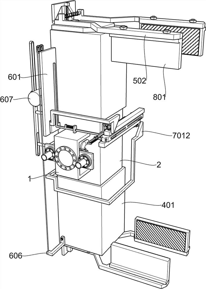
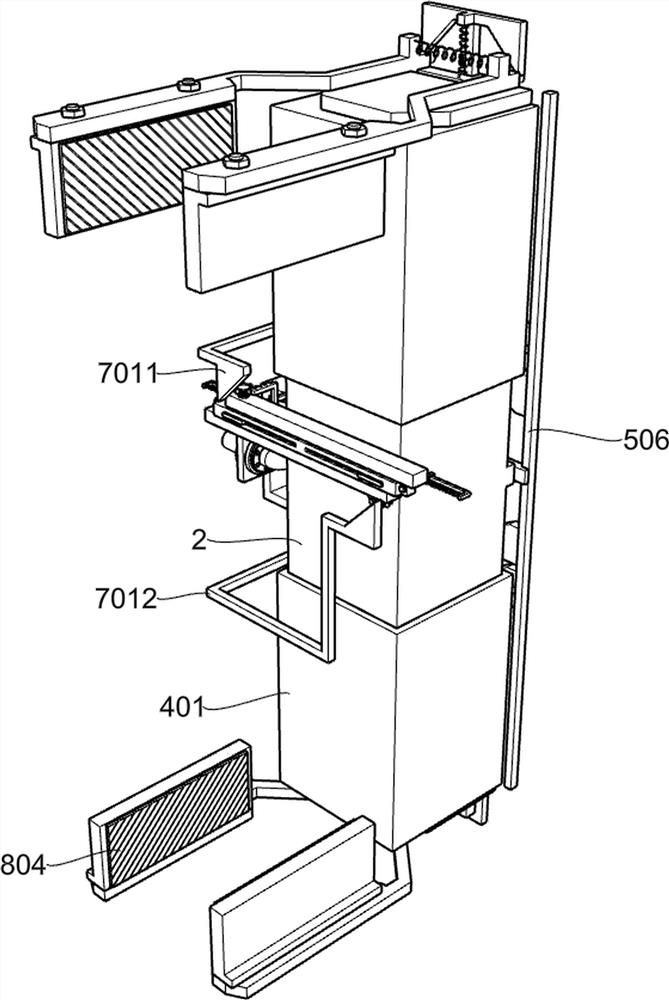
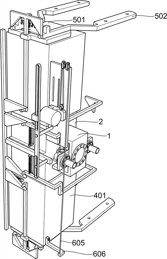
[0047] Such as figure 1 , figure 2 , image 3 , Figure 4 , Figure 5 , Image 6 , Figure 7 , Figure 8 , Figure 9 , Figure 10 with Figure 11 As shown, this embodiment proposes a retractable mechanical claw arm structure, including a U-shaped connecting plate 1, a return frame 2, a partition plate 3, a telescopic adjustment part 4, a mechanical gripping part 5 and a lever driving part 6 The back side of the U-shaped connecting plate 1 is fixedly connected with a return frame 2, and the top and bottom of the return frame 2 are provided with rectangular through holes. The middle part of the return frame 2 is fixedly connected with a partition plate 3, and ...


PUM


Abstract

The invention relates to a telescopic manipulator claw arm structure and belongs to the field of manipulators. The telescopic manipulator claw arm structure comprises a U-shaped connecting plate, a concentric-square-shaped frame, a partition plate, a telescopic adjusting component and the like. The hollow-square-shaped frame is fixedly connected to the rear side of the U-shaped connecting plate, the partition plate is fixedly connected to the middle in the hollow-square-shaped frame, the telescopic adjusting component is arranged on the hollow-square-shaped frame, and through cooperation of a movable pulley and other devices, the telescopic manipulator claw arm structure is adjusted to extend, meanwhile, the position of a pushing plate can move upwards, and the force application point of the pushing plate on a slotting swing rod moves upwards, so that a power arm is lengthened; therefore, the clamping force of the clamping strip to an object is increased, and the purpose of adjusting the clamping force according to the length of the object is achieved.

Description

technical field [0001] The invention belongs to the field of manipulators, and in particular relates to a retractable manipulator claw arm structure. Background technique [0002] In recent years, with the development of science and technology in my country and the expansion of the application scenarios of robotic arm technology, more and more robotic arms have been put into production. The robotic arm is a high-precision, high-speed Move to the specified coordinates in space to realize the functions provided by the execution parts, such as writing, picking up, testing and other functions. Due to the unique operational flexibility of the robotic arm, it has been widely used in industrial assembly, safety and explosion-proof and other fields. [0003] When the robotic arm is gripping an object, the claw arm of the robotic arm is the part that directly contacts the object. When the robotic claw arm performs the gripping task, due to the difference in the length and quality of t...

Claims


Application Information

Patent Timeline
IPC IPC(8): B25J15/00B25J15/08B25J15/02
CPCB25J15/0028B25J15/0052B25J15/08B25J15/0253
Inventor 韩小换雷灿彭正兴
Owner 湖南力云智能科技有限公司
Learn More