
Manual stamping device

A manual, mounting seat technology, applied in stamping, printing and other directions, can solve the problems of different contact pressures, it is difficult to ensure the parallelism of the official seal, and the display clarity of the seal is different, and achieves the effect of consistent clarity.

Pending Publication Date: 2020-12-04
CHONGQING JIANZHU COLLEGE
View PDF8 Cites 0 Cited by
  • Summary
  • Abstract
  • Description
  • Claims
  • Application Information

AI Technical Summary

Problems solved by technology

[0002] Stamping is an indispensable work procedure in the office. Currently, the official seal is manually placed on the document from top to bottom, but it is difficult for the operator to ensure that the bottom surface of the official seal is parallel to the surface of the document. When the official seal is placed on the document , the contact pressure between the bottom surface and the document is different, resulting in the problem that the display clarity of the seal is different

Method used


Image

  • Manual stamping device
  • Manual stamping device
  • Manual stamping device

Examples


Embodiment Construction

[0025] The present invention will be described in detail below in conjunction with the drawings and specific embodiments. It should be noted that in the drawings or descriptions, similar or identical parts use the same figure numbers, and implementations that are not shown or described in the drawings The method is a form known to those of ordinary skill in the art. In addition, the directional terms mentioned in the embodiments, such as "upper", "lower", "top", "bottom", "left", "right", "front", "rear", etc., are only for reference to the accompanying drawings. The directions are not intended to limit the protection scope of the present invention.

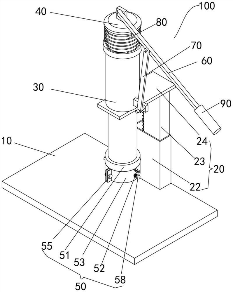
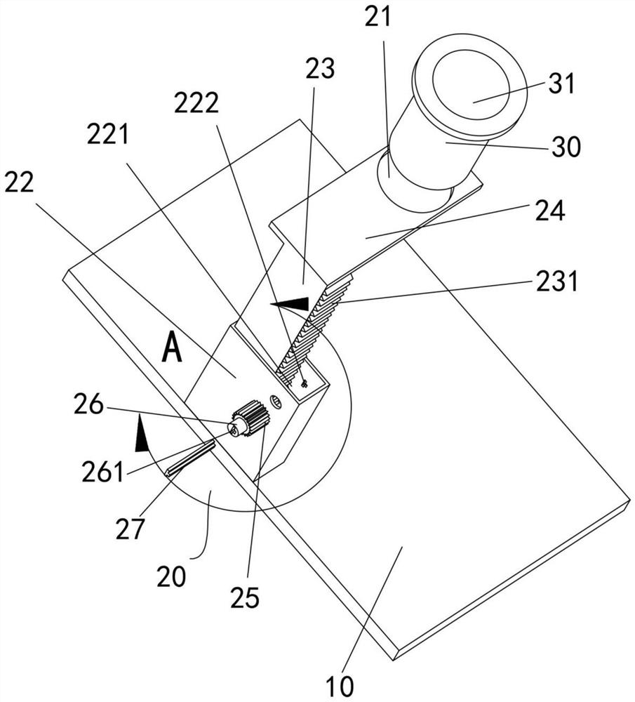
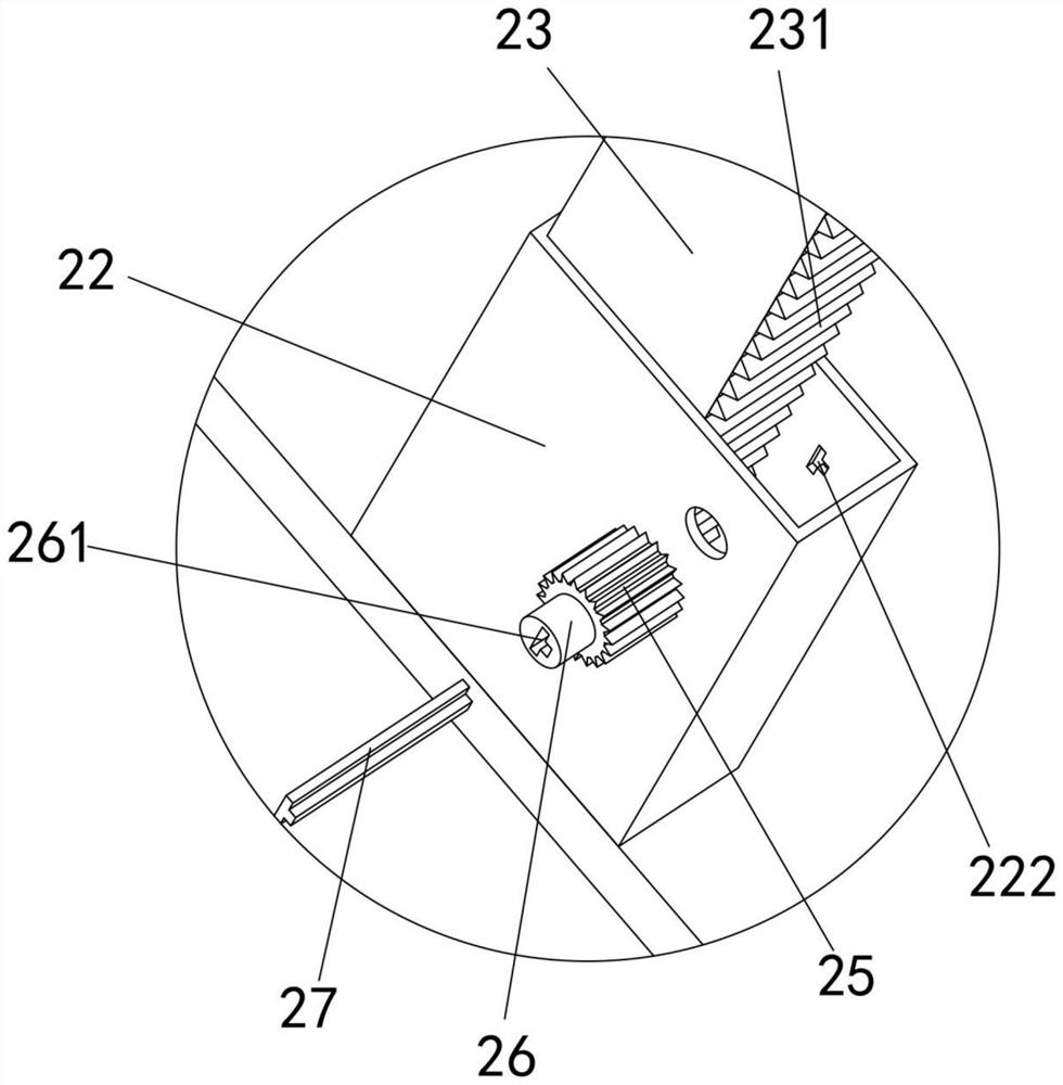
[0026] Such as Figure 1 to Figure 4 As shown, a manual stamping device 100 of the present invention includes a base 10 placed on the office work, the upper surface of the base 10 is fixed with a bracket 20,

[0027] Specifically, the bracket 20 includes a first column 22 , a second column 23 and a support plate 24 . The first...


PUM


Abstract

The invention relates to the technical field of office equipment, in particular to a manual stamping device. The manual stamping device comprises a base, a bracket, a sliding cylinder, a sliding rod,a mounting seat, a lever and a supporting rod, wherein the base is provided with a flat upper surface; the bracket is fixed above the base, and the bracket is L-shaped; a first through hole is formedin the upper surface of the bracket; the sliding cylinder is mounted in the first through hole, the longitudinal axis of the sliding cylinder is perpendicular to the upper surface of the base, and a second through hole is formed in the sliding cylinder; the sliding rod is located in the second through hole, and the sliding rod is in sliding connection with the sliding cylinder; the mounting seat is fixedly connected with the sliding rod and is positioned between the sliding cylinder and the base; one end of the lever is hinged with the upper end of the sliding rod; and one end of the supporting rod is hinged to the outer wall of the sliding cylinder, the other end of the supporting rod is hinged to the lever, and the distance from the hinged position of the lever and the sliding rod to thesupporting rod is smaller than that from the hinged position of the supporting rod and the lever to one section, far away from the sliding rod, of the lever.

Description

technical field [0001] The invention belongs to the technical field of office equipment, and in particular relates to a manual stamping device. Background technique [0002] Stamping is an indispensable work procedure in the office. Currently, the official seal is manually placed on the document from top to bottom, but it is difficult for the operator to ensure that the bottom surface of the official seal is parallel to the surface of the document. When the official seal is placed on the document , the contact pressure between the bottom surface and the document is different, resulting in the problem that the display clarity of the seal is different at each place. Contents of the invention [0003] The purpose of the present invention is to provide a manual stamping device, so that the operator can complete the stamping of documents with less effort, and keep the document and the bottom of the official seal parallel when stamping, so as to obtain stamps with consistent cla...

Claims


Application Information

Patent Timeline
Patent Type & Authority Applications(China)
IPC IPC(8): B41K3/04B41K3/62
CPCB41K3/04B41K3/62
Inventor 王玲黄霁何浪周健吴阳
Owner CHONGQING JIANZHU COLLEGE
Learn More