
Shell assembling equipment capable of achieving accurate dispensing for LED lamp production

A technology for LED lamps and assembly equipment, which is applied to mechanical equipment, devices for coating liquid on the surface, and material gluing. It can solve problems such as low processing efficiency, silica gel residue, and shell pollution, and achieve manpower saving and accurate dispensing. , to avoid the effect of wasting

Inactive Publication Date: 2020-12-04
DONGGUAN XIANGFEI INTELLIGENT EQUIP TECH CO LTD
View PDF0 Cites 18 Cited by
  • Summary
  • Abstract
  • Description
  • Claims
  • Application Information

AI Technical Summary

Problems solved by technology

[0004] Aiming at the deficiencies of the prior art, the present invention provides a shell assembly equipment for LED lamp production that can accurately dispense glue, which solves the problem of the dispensing head of the existing dispensing device proposed in the above background technology after one dispensing. There will be silicone residue inside, which is easy to drip and pollute the shell of the lamp body. In addition, the existing device first dispenses glue on the shell where the LED lamp is to be installed, and then performs patching operations on the place where the glue is dispensed, that is Glue is dispensed first, and then patch, and these two steps are usually carried out on two machine tools. After the glue is dispensed, the shell must be manually moved to the machine tool for patch, which is labor-intensive and the processing efficiency is not high.

Method used


Image

  • Shell assembling equipment capable of achieving accurate dispensing for LED lamp production
  • Shell assembling equipment capable of achieving accurate dispensing for LED lamp production
  • Shell assembling equipment capable of achieving accurate dispensing for LED lamp production

Examples


Embodiment Construction

[0026] The technical solutions in the embodiments of the present invention will be clearly and completely described below with reference to the accompanying drawings in the embodiments of the present invention. Obviously, the described embodiments are only a part of the embodiments of the present invention, but not all of the embodiments.

[0027] In the description of the present invention, unless otherwise stated, "plurality" means two or more; the terms "upper", "lower", "left", "right", "inner", "outer" The orientation or positional relationship indicated by , "front end", "rear end", "head", "tail", etc. are based on the orientation or positional relationship shown in the accompanying drawings, and are only for the convenience of describing the present invention and simplifying the description, not Indicates or implies that the referred device or element must have a specific orientation, be constructed and operate in a specific orientation, and therefore should not be cons...


PUM


Abstract

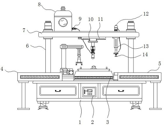
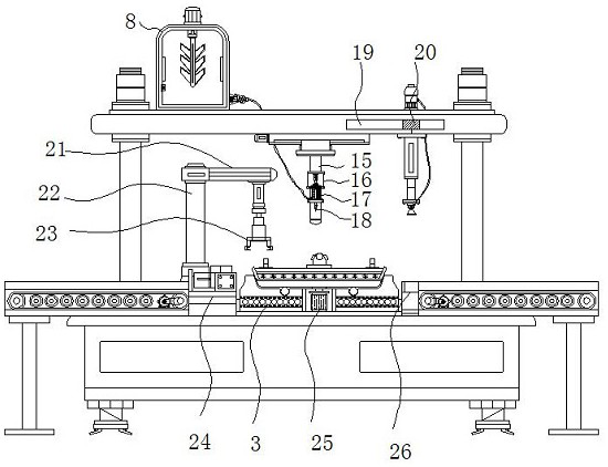
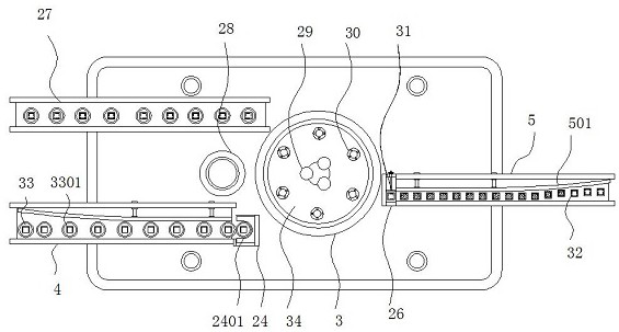
The invention discloses a shell assembling equipment capable of achieving accurate dispensing for LED lamp production. The shell assembling equipment particularly comprises a workbench, an operation table, a glue storage pipe and a grabbing mechanism, supporting columns are installed at the four corners of the top end of the workbench correspondingly, a top plate is fixed to the top ends of the supporting columns, and a silica gel storage tank is installed at one side of the top end of the top plate; and a vacuum pump is fixed to the other side of the top end of the top plate, an electromagnetic sliding rail is arranged at the side, close to the vacuum pump, of the interior of the top plate, a sliding block is installed in the electromagnetic sliding rail, a hydraulic lifting rod is fixedto the bottom end of the sliding block, and a vacuum suction cup is installed at the bottom end of the hydraulic lifting rod. According to the shell assembling equipment capable of achieving accuratedispensing for LED lamp production, through the arrangement of the electromagnetic valve, a hydraulic rod and a piston, after one-time dispensing is finished, the hydraulic rod can drive the piston tomove upwards, silica gel in a glue injection head is sucked back into the glue storage pipe, and the situation that the residual silica gel in the glue dispensing head drips and pollutes a shell of alamp body is avoided.

Description

technical field [0001] The invention relates to the technical field of LED lamp production, in particular to a housing assembly device for LED lamp production that can accurately dispense glue. Background technique [0002] The LED industry is one of the most watched industries in recent years. Up to now, LED products have the advantages of energy saving, power saving, high efficiency, fast response time, long life cycle time, no mercury, and environmental protection benefits. When the lamp is produced, it is necessary to apply thermal conductive silica gel on the back of the aluminum substrate, and then fix the aluminum substrate on the shell to fix the LED light source. [0003] After one dispensing of the existing glue dispensing device, there will be residual silica gel inside the dispensing head, which is easy to drip and cause pollution to the shell of the lamp body. In addition, the existing device is first to install the LED lamp on the shell of the place. Dispensin...

Claims


Application Information

Patent Timeline
IPC IPC(8): B05C5/02B05C11/00B05C13/02F16B11/00
CPCB05C5/0225B05C11/00B05C13/02F16B11/006
Inventor 邓珊王龙陈创佳
Owner DONGGUAN XIANGFEI INTELLIGENT EQUIP TECH CO LTD
Learn More