
Angiocardiography device

A cardiovascular and catheter technology, applied in the field of cardiovascular imaging devices, can solve the problems of increasing the degree of contrast medium adhesion, slow injection work, high viscosity of contrast medium, etc., and achieve the effect of reducing discomfort and convenient use

Inactive Publication Date: 2020-12-04
许永刚
View PDF7 Cites 0 Cited by
  • Summary
  • Abstract
  • Description
  • Claims
  • Application Information

AI Technical Summary

Problems solved by technology

[0002] In the basic operation of the current radiography operation, the catheter is inserted into the patient's blood vessels and corresponding body chambers, and then the contrast agent is injected into the radiography work. The device currently used is a syringe, but the viscosity of the contrast agent is extremely high. It is very laborious to inject the push-type syringe. In addition, during the imaging process, the injection work needs to be carried out slowly, otherwise it will cause danger. During the injection, the contrast agent sticks together and cannot be spread out quickly when it enters the corresponding chamber. The time for follow-up inspection is increased, and the current push-and-push injection method has major defects
In addition, when the weather is relatively cold, the degree of adhesion of the contrast agent is increased, and it is more difficult to inject such as in the patient's body.
[0003] Most of the angiography methods currently on the market are manual syringe angiography. Because it is manual injection, and because each person's strength is different, the injection flow rate is also different during the injection process. Due to the high density of the contrast agent itself , is a viscous liquid, the injection flow rate is relatively slow, and the entire injection time is also long, and at the same time, the flow rate cannot be maintained at a uniform and stable level; and most of the traditional devices of this type do not have the function of contrast agent heating. It is easy to make the patient feel uncomfortable and increase the tension. The patient's injection site is not well supported during the injection, which will make the patient feel tired

Method used


Image

  • Angiocardiography device
  • Angiocardiography device
  • Angiocardiography device

Examples


Embodiment Construction

[0032] The technical solutions in the embodiments of the present invention will be clearly and completely described below with reference to the accompanying drawings in the embodiments of the present invention. Obviously, the described embodiments are only a part of the embodiments of the present invention, but not all of the embodiments. Based on the embodiments of the present invention, all other embodiments obtained by those of ordinary skill in the art without creative efforts shall fall within the protection scope of the present invention.

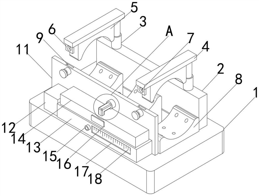
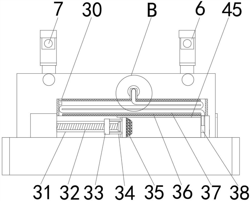
[0033] see Figures 1 to 7In the embodiment of the present invention, a cardiovascular angiography device includes a bottom plate 1 and a second baffle 11 fixedly connected to one side of the upper surface of the bottom plate 1. One side of the second baffle 11 is provided with a liquid storage frame 13, which stores liquid The frame 13 is fixedly connected with the upper surface of the bottom plate 1, the upper end of the liquid stor...


PUM


Abstract

The invention discloses an angiocardiography device. The angiocardiography device comprises a bottom plate and a second baffle fixedly connected to one side of the upper surface of the bottom plate, wherein a liquid storage frame is arranged on one side of the second baffle and fixedly connected with the upper surface of the bottom plate; a heating groove is fixedly connected to the upper end of the liquid storage frame; a speed adjusting motor is arranged on one side of the liquid storage frame; a first connecting rod is fixedly connected to one side in the liquid storage frame; a groove is formed in the middle of the first connecting rod; and a liquid storage cylinder is arranged on one side of the first connecting rod. The speed adjusting motor is arranged and drives a lead screw to rotate, and therefore a sliding block on the outer side of the lead screw slides in the groove; the sliding speed of the sliding block can be adjusted by changing the rotating speed of the speed adjusting motor, then the pushing speed of a pushing plug can be changed, and then the injection speed is changed; and the speed adjusting motor drives the sliding block to conduct injection, and the uniformspeed can be kept during injection.

Description

technical field [0001] The invention relates to an imaging device, in particular to a cardiovascular imaging device. Background technique [0002] In the basic operation of the current angiography operation, the catheter is inserted into the blood vessel and the corresponding body cavity of the patient, and then the contrast agent is injected for angiography. The currently used device is a syringe, but the viscosity of the contrast agent is extremely high. It is very laborious to inject with a push-type syringe. In addition, during the imaging process, the injection work needs to be carried out slowly, otherwise it will cause danger. During the injection, the contrast agent sticks together and cannot be spread quickly when it enters the corresponding chamber. The time for follow-up inspection is increased, and the current push injection method has major defects. In addition, when the weather is relatively cold, the degree of adhesion of the contrast agent is further increas...

Claims


Application Information

Patent Timeline
IPC IPC(8): A61M5/20A61M5/31A61M5/315A61M5/44A61M5/52A61M25/02A61L2/18
CPCA61M5/52A61M5/20A61M5/445A61L2/18A61M25/02A61M5/31A61M5/31578A61L2202/24A61M2025/028A61M2025/024
Inventor 许永刚
Owner 许永刚
Learn More