High-power power supply equipment state monitoring device and using method

A high-power power supply and equipment status technology, applied in emergency protection devices, circuits, electrical components, etc., can solve problems such as disconnection of wires and blades, user electric shock, difficult fuses, etc., to ensure normal operation, improve construction speed, The effect of preventing the wire from falling off

Active Publication Date: 2020-12-01
河源市省科院研究院 +1
View PDF10 Cites 0 Cited by
  • Summary
  • Abstract
  • Description
  • Claims
  • Application Information

AI Technical Summary

Problems solved by technology

[0003] The current monitoring devices for high-power power supply equipment generally protect the power supply equipment and lines through the fuse inside the switch blade. After burning out, it is necessary to remove the screw on the conductive seat of the switch knife and replace it with a new fuse before it can be used. The internal space of the switch knife is small, which makes it inconvenient to install the alloy fuse. It is difficult to quickly replace the new fuse during emergency construction, which affects high power. The use of power supply equipment, and the incoming and outgoing wires on the switch blade are simply fixed by screws. During construction, it is necessary to drag the switch blade and the wire for a long time, which may easily cause the wire and the switch blade to be separated.
On the one hand, it affects the use of the equipment, on the other hand, it is easy to cause electric shock to the user. There is no protective mechanism on the switch knife used outdoors, and it is easy to get an electric shock when it is used in rainy days.

Method used


Image

  • High-power power supply equipment state monitoring device and using method
  • High-power power supply equipment state monitoring device and using method
  • High-power power supply equipment state monitoring device and using method

Examples


Embodiment Construction

[0030] In order to make the technical means, creative features, goals and effects achieved by the present invention easy to understand, the present invention will be further described below in conjunction with specific embodiments.

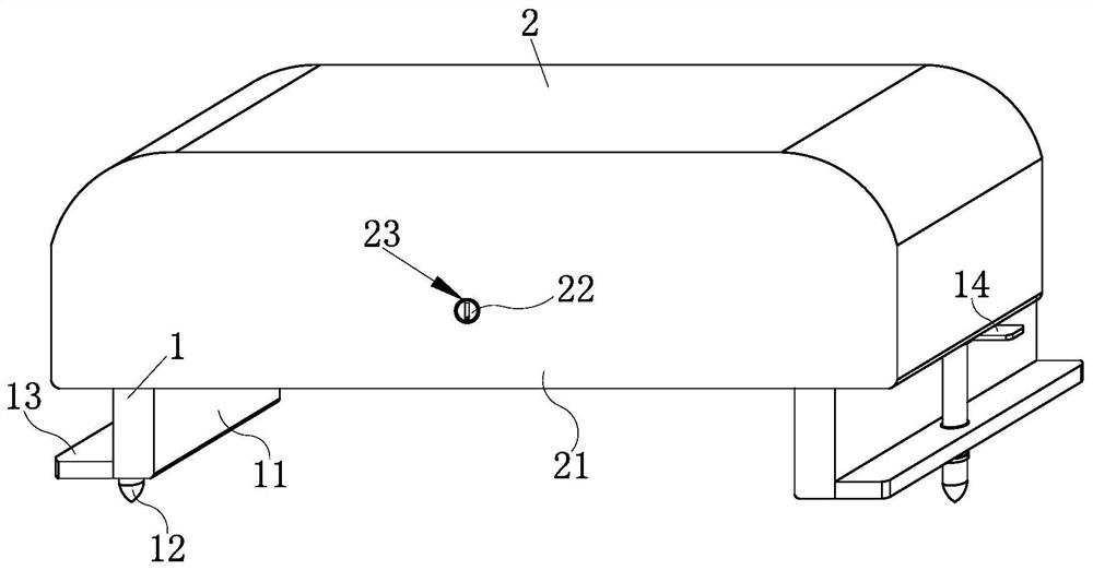
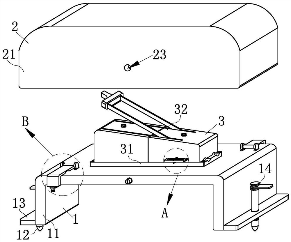
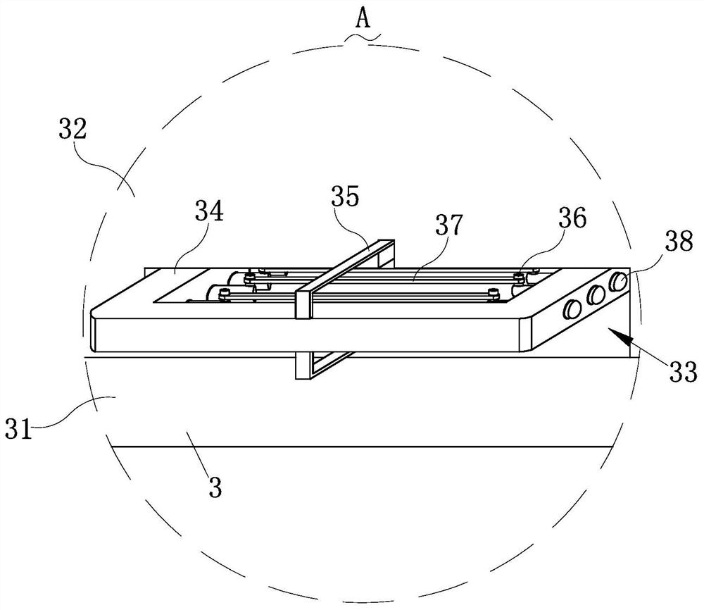
[0031] Such as Figure 1-Figure 8 As shown, a high-power power supply device status monitoring device according to the present invention includes a support mechanism 1, a protection mechanism 2, a protection mechanism 3 and a wire pressing mechanism 4, which are used to realize the support mechanism 1 supporting the overall mechanism. The protection mechanism 3 for protecting power supply equipment and lines is installed on the surface, and the surface of the support mechanism 1 is installed with two wire crimping mechanisms 4 for reinforcing the electric wires on the protection mechanism 3, The two crimping mechanisms 4 located on the surface of the support mechanism 1 are arranged diagonally, and the side of the support mechanism 1 is installed ...


PUM


Abstract

The invention belongs to the technical field of high-power power supply equipment monitoring and relates to a high-power power supply equipment state monitoring device and a using method. The device comprises a supporting mechanism, a safeguard mechanism, a protection mechanism and wire pressing mechanisms; the surface of the supporting mechanism is provided with the protection mechanism for controlling the switching on and switching off of a circuit; the supporting mechanism fixes the protection mechanism; the protection mechanism can rapidly replace a damaged fuse wire during emergency construction, normal operation of construction is guaranteed, and the construction speed is increased; the two wire pressing mechanisms are diagonally mounted on the surface of the supporting mechanism andcan fix wires at the two ends of the protection mechanism, so that the wires are prevented from falling off from the two ends of the protection mechanism when power equipment is used, normal power supply of the equipment is guaranteed, and electric leakage is avoided; and the safeguard mechanism is installed at the top of the supporting mechanism, so that the protection mechanism can be protectedduring outdoor construction in rainy days, and the situation that the power equipment cannot be used due to rainwater entering the power equipment is avoided.

Description

technical field [0001] The invention relates to the technical field of high-power power supply equipment monitoring, in particular to a high-power power supply equipment state monitoring device and a using method. Background technique [0002] The physical definition of power is the work done by a machine per unit of time. The amount of work is certain, the shorter the time, the greater the power value, the maximum output power is also called instantaneous power, or peak power. For power amplifiers, the maximum output power refers to the maximum power that the power amplifier can output when a sufficiently large signal is input to the power amplifier within a certain harmonic distortion index and the volume and tone potentiometers are adjusted to the maximum. It is the power value of the car power amplifier when no physical damage or electrical damage occurs in a very short time (usually only a few milliseconds) without considering the distortion. The high-power switching p...

Claims


Application Information

Patent Timeline
Patent Type & Authority Applications(China)
IPC IPC(8): H01H21/56H01H21/16H01H21/04H01H21/12H01H85/22
CPCH01H21/56H01H21/16H01H21/04H01H21/12H01H85/22
Inventor 姚岛陈光黎雷禹雷久淮王微林驹
Owner 河源市省科院研究院
Why Eureka
Try Eureka