A lifting device for control engineering

A technology for controlling engineering and lifting devices, applied in the direction of lifting devices, etc., can solve the problems of inconvenient movement and inability to fully meet the needs of use, and achieve the effect of improving convenience

Active Publication Date: 2021-10-26
JIANGSU SECURITY TECH CARRER ACADEMY
View PDF18 Cites 1 Cited by
  • Summary
  • Abstract
  • Description
  • Claims
  • Application Information

AI Technical Summary

Problems solved by technology

[0003] However, most of the control engineering lifting devices in the prior art realize lifting through the scissor lifting platform, but the vertical lifting of the workbench can only be realized through the scissor lifting platform, and the vertical lifting can not fully meet the needs of use. When working at heights, if the control engineering equipment is simply raised to a specific height, then the operators located around need to change positions to meet the use of the control engineering equipment, and it is very inconvenient for people to move in the sky, so if the lifting device Only being able to realize the lifting function does not meet the needs of use

Method used


Image

  • A lifting device for control engineering
  • A lifting device for control engineering
  • A lifting device for control engineering

Examples


Embodiment 1

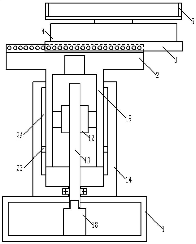
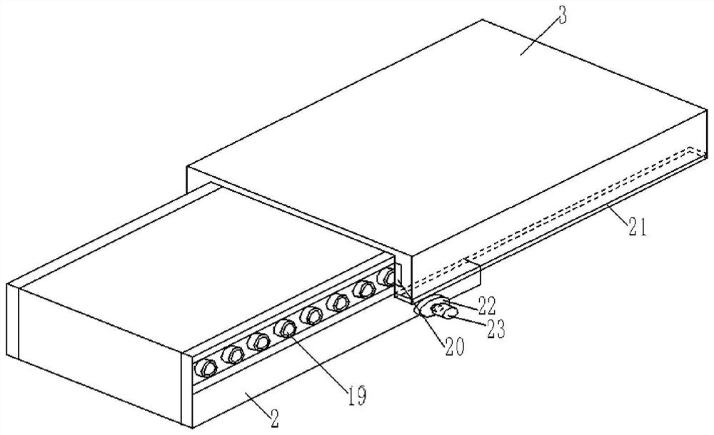
[0049] See figure 1 , is a structural schematic diagram of a lifting device for control engineering in an embodiment. Including: a base 1; a lifting mechanism, the fixed end of which is fixed on the upper surface of the base 1; a first plate body 2 connected to the output end of the lifting mechanism, and the lifting mechanism drives the first plate body 2 to rise relative to the base 1 Down; translation mechanism, its fixed end is fixed on the first plate body 2; the second plate body 3 is connected with the output end of the translation mechanism, and the translation mechanism drives the second plate body 3 along the first plate body 2 sliding left and right; the housing 4 is fixed on the upper surface of the second board 3; the intermittent rotation mechanism is located inside the housing 4 as a whole, and its fixed end is connected with the housing 4; the workbench 5 is its The upper surface is provided with control engineering equipment, which is located above the housin...

Embodiment 2

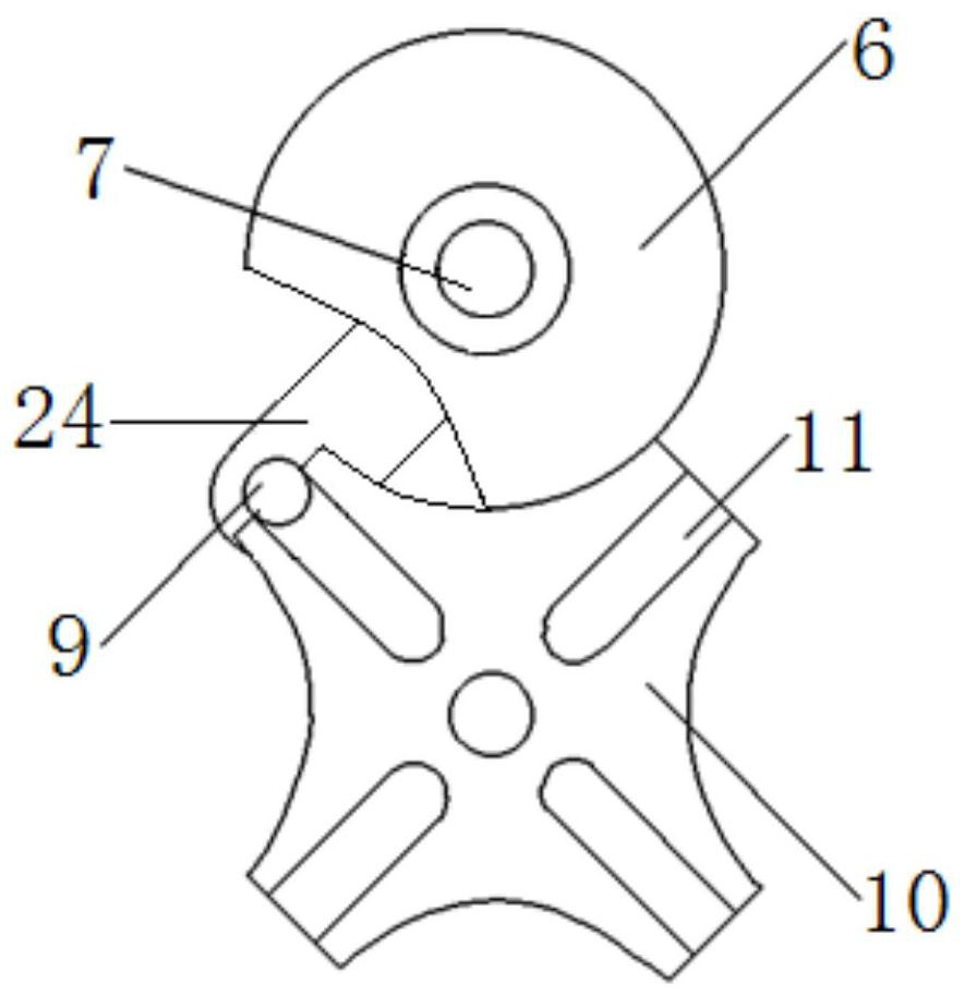
[0052]This embodiment is based on Embodiment 1, and the intermittent rotation mechanism includes: a driving dial 6, the lower surface of which is connected to the housing 4 through a plane thrust bearing, and the plane thrust bearing is clipped into a recess opened on the housing 4. In the groove; the first rotating shaft 7 runs through the driving dial 6 and is fixedly connected with the driving dial 6; the upper and lower ends of the first rotating shaft 7 are respectively connected to the housing 4 through a bearing; the first motor 8 , is connected with one end of the first rotating shaft 7, and the first motor 8 is fixed inside the housing 4; the round pin 9 is connected with the driving dial 6 through the connecting rod 24; the driven sheave 10 is connected with the The driving dial 6 is matched, and the driven sheave 10 is provided with a radial groove 11 that is matched with the round pin 9; Fixedly connected, the upper and lower ends of the second rotating shaft 17 ar...

Embodiment 3

[0055] This embodiment is based on Embodiment 1, and the lifting mechanism includes: a column 14, which is a hollow shell structure fixed on the upper surface of the base 1; a lifting column 15, which is also a hollow shell structure, is sleeved on the column 14, and is slidingly connected with the column 14 through a sliding assembly; the screw 13 is placed longitudinally inside the lifting column 15, the lower end of the screw 13 passes through the column 14 and the base 1 in turn, and the lower end of the screw 13 Connected with the column 14 through a bearing; the nut 12 is sleeved on the outside of the screw 13 and screwed with the screw 13, and the nut 13 is also connected with the lifting column 15 through the connecting plate 16; the second motor 18, whose output The shaft is connected with the lower end of the screw rod 13 , and the second motor 18 is fixed inside the base 1 .

[0056] Further, the sliding assembly includes: a sliding block 25 fixed on the left and ri...


PUM


Abstract

The invention provides a lifting device for control engineering, comprising: a base; a lifting mechanism, the fixed end of which is fixed on the upper surface of the base; a first plate connected to the output end of the lifting mechanism, and the lifting mechanism drives the first plate to The base rises and falls; the translation mechanism, whose fixed end is fixed on the first board; the second board, connected with the output end of the translation mechanism, and the translation mechanism drives the second board to slide left and right along the first board; the shell, fixed On the upper surface of the second plate body; the intermittent rotation mechanism is located inside the casing as a whole, and its fixed end is connected to the casing; the workbench, whose upper surface is provided with control engineering equipment, is located above the casing, and the output of the intermittent rotation mechanism The end is fixedly connected with the workbench; the invention provides a control engineering equipment that can not only smoothly drive the control engineering equipment up and down, but also drive its translation and intermittent rotation, so that the control engineering equipment can meet the needs of multi-station workers. lifting device.

Description

technical field [0001] The invention relates to the technical field of control engineering equipment, in particular to a lifting device for control engineering. Background technique [0002] The lifting device of the control engineering is a lifting device that drives the control equipment to rise and fall. The lifting device is a lifting machine for transporting people and objects, and also refers to the equipment for vertical transportation in logistics systems such as factories and automatic warehouses. The lifting platform is often equipped with There are a variety of plane conveying equipment, which are used as connecting devices for conveying lines at different heights; lifting devices are not only used for conveying goods at different heights, but also widely used in high-altitude installation, municipal maintenance, docks, logistics transportation, building decoration and other projects; [0003] However, most of the control engineering lifting devices in the prior a...

Claims


Application Information

Patent Timeline
Patent Type & Authority Patents(China)
IPC IPC(8): B66F11/00
CPCB66F11/00
Inventor 李庆黄传翔
Owner JIANGSU SECURITY TECH CARRER ACADEMY
Why Eureka
Try Eureka