
Telescopic crank device of bicycle

A bicycle and crank technology, applied in the crank structure, vehicle parts, transportation and packaging, etc., can solve the problem of increasing the burden

Inactive Publication Date: 2020-12-01
张连科 +1
View PDF4 Cites 1 Cited by
  • Summary
  • Abstract
  • Description
  • Claims
  • Application Information

AI Technical Summary

Problems solved by technology

[0006] Retrieve the relevant creations that have been published so far, and most of the above-mentioned utility models or inventions use a central shaft cam groove to realize the telescopic function. Among them, the Korean gear transmission that makes the crank telescopic is the only invention that has not been used. The creation of the cam groove on the center shaft; however, the relevant creations that have been retrieved and published all have a sense of increased burden, such as setting a large cam groove plate at the center shaft to link the telescopic crank. The structure seems simple, but for bicycles The overall visual beauty seems to cast a shadow over it, and while providing a telescopic crank to create a labor-saving structure, will the increased frictional resistance caused by the full cycle of the left and right cranks offset part of the increase due to the extension of the moment arm? This is a subject worth pondering and discussing to solve the difficulties faced by billions of cyclists in the world

Method used


Image

  • Telescopic crank device of bicycle
  • Telescopic crank device of bicycle
  • Telescopic crank device of bicycle

Examples


Embodiment Construction

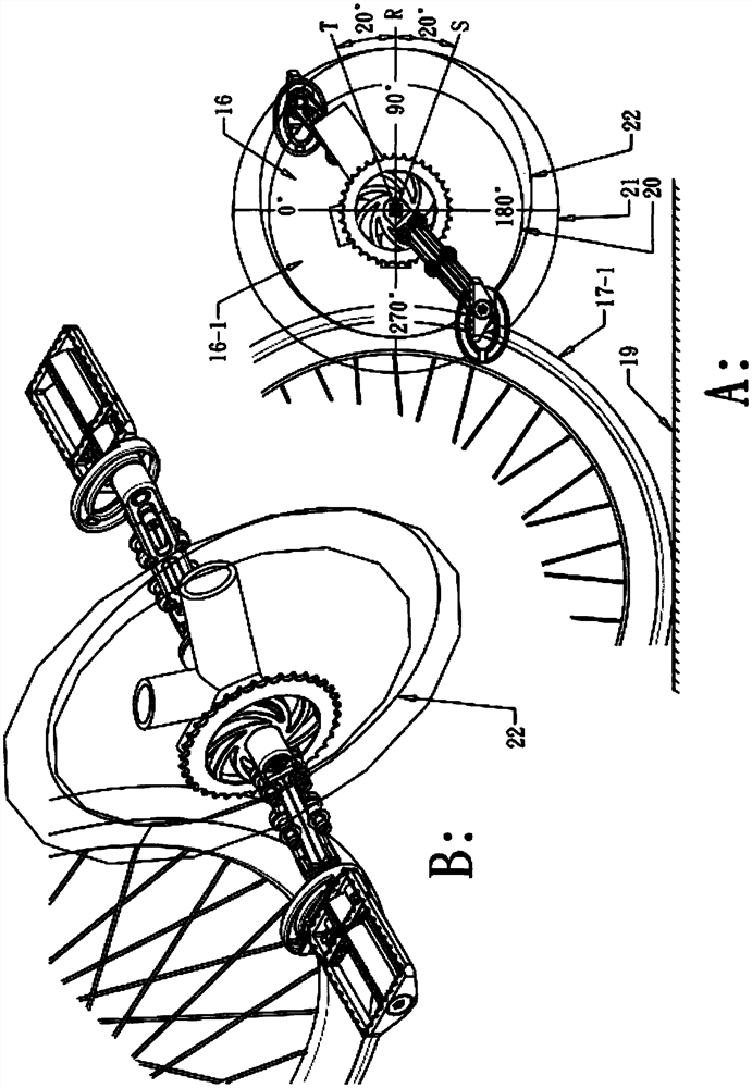
[0157] A telescopic crank device for a bicycle, which can realize a longer crank arm when the pedals are rotated to the effective force application range 16 when riding, so as to increase the pedaling torque and help overcome physical exertion when pedaling starts and uphill sections riding environment conditions; and in the unapplied range 16-1, it has the shortest crank arm, which makes riding more brisk and comfortable;

[0158] A: The first embodiment of the present invention, such as figure 1 , 2 , 3, for:

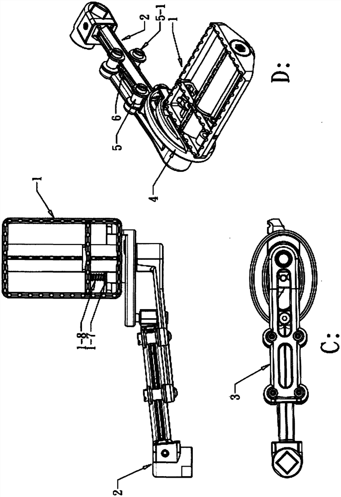
[0159] A telescopic crank cam disc device for a bicycle, comprising a pedal 1, a fixed crank 2, a telescopic crank 3, and a cam disc 4 with a center hole offset type feature;

[0160] Principle: In order to apply the fitting contact between the bottom of the rider's foot and the pedal 1, accept the continuous force exerted by the bottom of the rider's foot, and give the pedal 1 an angle benchmark that is the same as the force-applied part of the rider's foot, throu...


PUM


Abstract

The invention discloses a telescopic crank device of a bicycle. The crank can be operated and controlled when the bicycle is ridden. The foot treading moment is increased by using the function of thetelescopic crank in case of starting or climbing a hill, a hip bending angle force application form and a knee bending angle force application form which accord with ergonomics are adopted, an elliptical telescopic crank track is provided; the force application area during treading circulation is the longest force arm; when the bicycle enters a treading cycle, a non-force-applying area is the shortest force arm so that fatigue and physical exhaustion of thighs and shanks are further reduced, besides low-speed gear selection of a chain transmission, one more choice is provided for riding, and vast bicycle enthusiasts can face a large amount of physical load during starting or climbing more easily; when high-speed riding is carried out, on the premise that high-speed pedaling frequency is required, stopping-free adjustment can be achieved, the circular motion trail of the shortest crank can be controlled in the riding process, the large-span amplitude burden of thighs and shanks in the high-speed riding process is reduced, and the pedaling frequency rate is increased.

Description

technical field [0001] The invention relates to a crank device of a bicycle, which provides a labor-saving technical field for increasing the torque of the force-applying section when riding a bicycle, and specifically provides a retractable crank device, which is used to drive the bicycle with the minimum pedaling cycle track and provides the maximum torque. technical means to move forward. Background technique [0002] Such as Figure 16 , is a fixed crank device of an existing commercially available bicycle, in order to circulate the kinetic energy of the bicycle rider's pedal in a circular form, and give the kinetic energy when stepping forward as a force section, and the pedal crank is a full circle, etc. Long operating form; and we all know that the longer the crank length, the greater the torque given when pedaling, which helps to reduce the power to be paid when riding a bicycle. The range of circular motion is increased synchronously, and it also increases the load...

Claims


Application Information

Patent Timeline
Patent Type & Authority Applications(China)
IPC IPC(8): B62M3/02
CPCB62M3/02
Inventor 张连科李妙真
Owner 张连科
Learn More