
Shaft end oil separating and discharging structure of cone crusher

A cone crusher and shaft end technology, which is applied to mechanical equipment, engine components, engine seals, etc., can solve problems such as oil leakage, oil waste, and poor lubrication effect, and achieve the effect of ensuring lubrication

Pending Publication Date: 2020-12-01
成都市新力设备制造有限责任公司
View PDF0 Cites 0 Cited by
  • Summary
  • Abstract
  • Description
  • Claims
  • Application Information

AI Technical Summary

Problems solved by technology

Since the oil itself has a certain viscosity, and the oil delivery hole in the eccentric shaft basically runs through the entire eccentric shaft, the length of the oil delivery hole is very long, resulting in a high pressure of the oil in the oil delivery hole, and the pressure is too high during oil delivery. It is easy to cause a large amount of oil to leak from the copper sleeve at the top of the eccentric shaft; especially with the use of the cone crusher, the copper sleeve at the top of the eccentric shaft is gradually worn, and the oil leakage will increase
Eventually, a large amount of oil is wasted, and at the same time, oil leakage leads to problems of low cooling efficiency and poor lubrication in the cone crusher, which leads to a significant shortening of the service life of the cone crusher

Method used


Image

  • Shaft end oil separating and discharging structure of cone crusher
  • Shaft end oil separating and discharging structure of cone crusher
  • Shaft end oil separating and discharging structure of cone crusher

Examples


Embodiment Construction

[0017] The present invention is further described below in conjunction with the accompanying drawings, but the scope of protection of the present invention is not limited to the following.

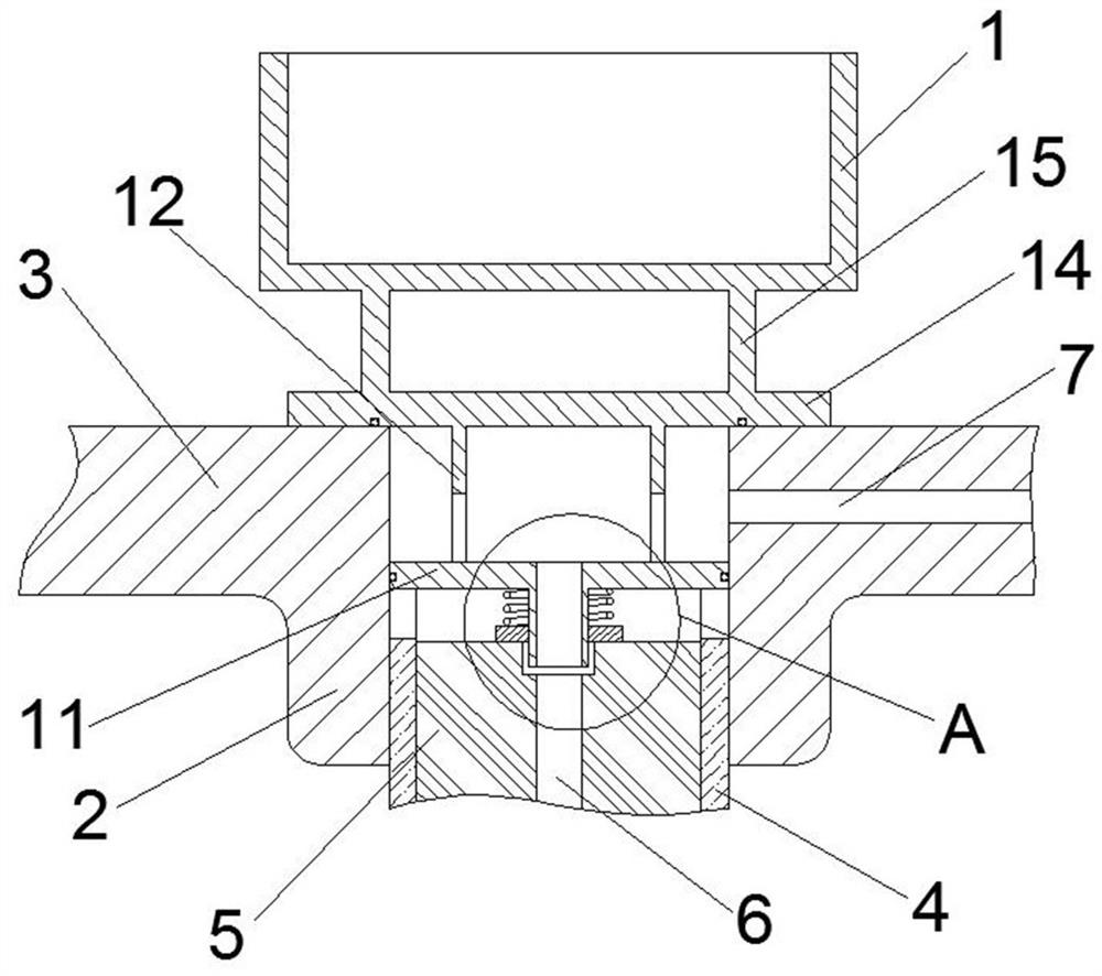
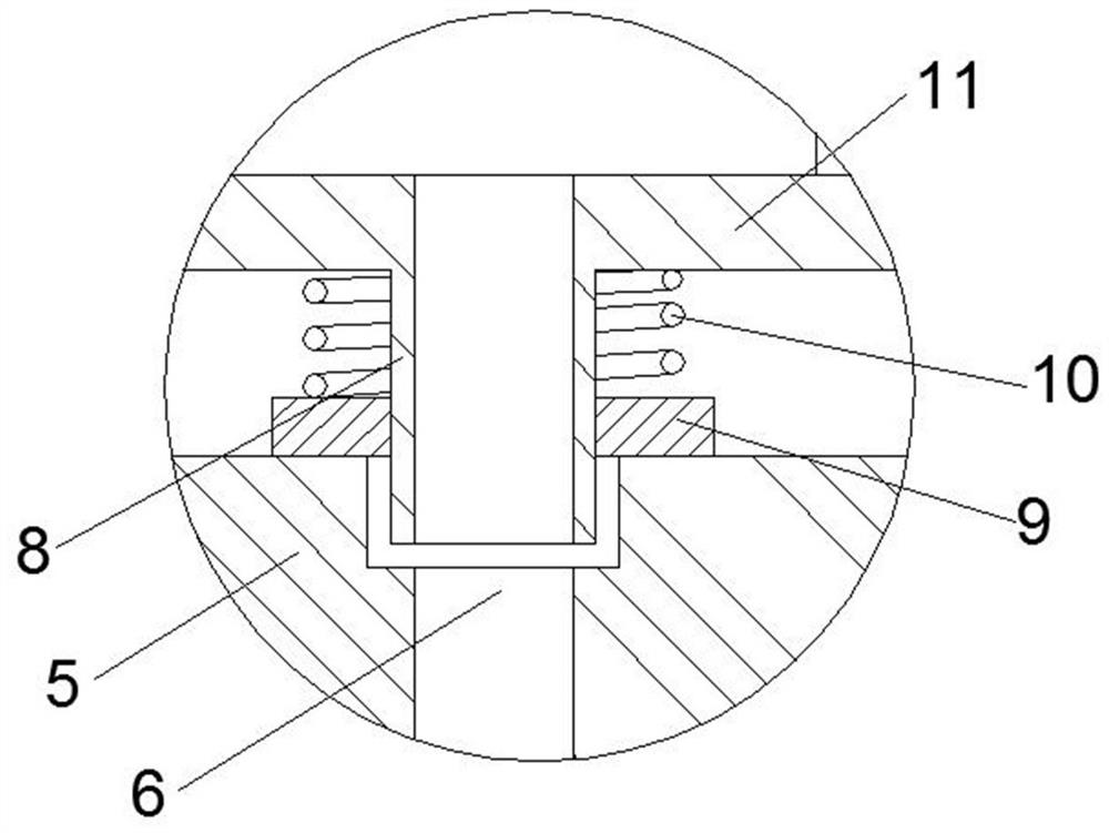
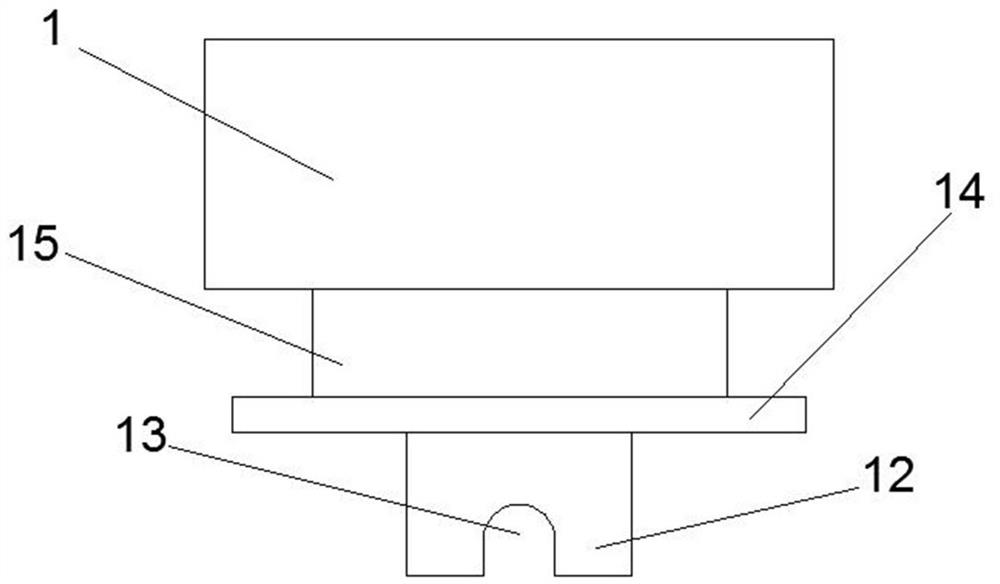
[0018] as Figure 1 As shown, a cone crusher shaft end oil distribution oil structure, the structure is located in the top of the eccentric shaft 5 of the cone crusher and the upper frame of the cone crusher connection, the upper frame body is connected to the cone crusher body through the outer ring, the middle of the upper frame is provided with a ring seat 2 for fixing the eccentric shaft 5, the ring seat 2 and the outer ring are connected by a number of stiffeners 3, the role of the ring seat 2 is used to fix the upper end of the eccentric shaft 5, the ring seat 2 is provided with a copper sleeve 4, the copper sleeve 4 inner ring and the eccentric shaft 5 upper end is connected. The upper frame itself does not move, and the relative rotation occurs between the eccentric shaft 5 and the copper...


PUM


Abstract

The invention relates to a shaft end oil separating and discharging structure of a cone crusher. An oil inlet path is arranged in a reinforcing rib (3) of an upper frame body; meanwhile, an oil seal ring (9) is arranged above an eccentric shaft (5); oil entering from the oil inlet path is injected into an oil conveying hole (6) through an oil injection pipe (8); the lower end of the oil injectionpipe (8) penetrates through the oil seal ring (9) and then is inserted into the oil conveying hole (6); and the oil seal ring (9) can prevent a large amount of oil from leaking between the top end ofthe eccentric shaft (5) and a copper sleeve (4) or between the copper sleeve (4) and an annular base (2). The oil seal ring (9) is in clearance fit with the outer cylindrical surface of the oil injection pipe (8), so that a small amount of oil is allowed to pass, and the purpose of lubricating the top of the eccentric shaft (5) and the copper sleeve (4) is achieved. An annular space exists betweenthe top end of the oil conveying hole (6) and the outer cylindrical face of the oil injection pipe (8), and even if the copper sleeve (4) is abraded, the eccentric shaft (5) swings in the operation process and cannot collide with and damage the oil injection pipe (8).

Description

Technical field [0001] The present invention relates to the technical field of cone crusher, in particular a cone crusher shaft end oil separation oil structure. Background [0002] Due to the crushing method and transmission mode, the cone crusher needs to continuously input oil for cooling and lubrication. Due to the vertical setting of the eccentric shaft structure of the cone crusher, the oil path for conveying oil is set in the eccentric shaft, and then the oil pipeline is arranged to transfer oil to the top of the eccentric shaft. Because the oil itself has a certain viscosity, and the oil transfer hole in the eccentric shaft basically runs through the entire eccentric shaft, the length of the oil transfer hole is very long, resulting in a high pressure of the oil in the oil inlet, and the pressure is too high during oil transfer, which can easily lead to a large amount of oil leaking from the copper sleeve at the top of the eccentric shaft; especially with the use of the c...

Claims


Application Information

Patent Timeline
Patent Type & Authority Applications(China)
IPC IPC(8): B02C2/04B02C23/00F16J15/02
CPCB02C2/04B02C23/00F16J15/02
Inventor 肖功方
Owner 成都市新力设备制造有限责任公司
Learn More