Design method of thick-wall part optical system comprising diffusion hole for eliminating dark area at chamfer

A design method and optical system technology, applied in optics, optical components, instruments, etc., can solve problems such as unevenness and dark areas

Active Publication Date: 2020-11-27
MAGNETI MARELLI AUTOMOTIVE COMPONENTS WUHU
View PDF11 Cites 0 Cited by
  • Summary
  • Abstract
  • Description
  • Claims
  • Application Information

AI Technical Summary

Problems solved by technology

[0003] Aiming at the deficiencies in the prior art, the purpose of the present invention is to provide a design method for the optical system of the thick-walled part that includes the diffusion hole that eliminates the dark area at the chamfer, by changing the collimation hole of the existing thick-walled part to Diffusion hole, or changing the collimation surface to a diffusion surface, through the diffusion hole and the diffusion surface to disperse the light, so that the area of ​​the dark area caused by the chamfering of the original collimation hole is covered by the light scattered by the diffusion hole , and the coverage of the dark area is obtained through the precise calculation of the previous design, so it can well improve and solve the problem of dark area and unevenness of the conventional optical structure

Method used


Image

  • Design method of thick-wall part optical system comprising diffusion hole for eliminating dark area at chamfer
  • Design method of thick-wall part optical system comprising diffusion hole for eliminating dark area at chamfer
  • Design method of thick-wall part optical system comprising diffusion hole for eliminating dark area at chamfer

Examples


Embodiment 1

[0050] This embodiment provides a design method for thick-walled parts including primary collimation and secondary collimation.

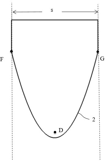
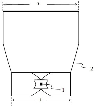
[0051] 1.( Figure 1 ~ Figure 4 As shown) After getting the customer's car light shape input, the width s of a single collimator can be determined by the width of the thick-walled part and the number of light sources given by the customer (s=width of the thick-walled part / number of light sources); as everything The position D of the light source 1 of the initially selected reference of the design, the side wall 2 that can be obtained according to the focal length and the light source position D, and the width t of the primary collimation structure of the thick-walled part, in the design principle and method of the present invention, By default, the width s of a single collimator, the position of the light source D, the side wall 2, and the width t of the primary collimation structure of thick-walled parts are known parameters. The maximum vertical ...

Embodiment 2

[0082] This embodiment provides a design method for a thick-walled part that does not include primary collimation but only has secondary collimation. The overall design principles and steps are the same as those of the above-mentioned thick-walled part that includes primary collimation and secondary collimation. , the different concepts are described as follows:

[0083] Such as Figure 20 As shown, different from the first article of the thick-walled part that includes primary and secondary collimation, this case defaults to known parameters including a single collimator width s, light source position D, and side wall 2, excluding primary Align thick wall part width.

[0084] The position of the light source 1, which is the initially selected reference for all designs, is the actual position, and there is no need to use the concept of virtual focus.

[0085] Scaling is not required in the design (including theoretical design and design of fine-tuning after entering the simu...

Embodiment 3

[0087] Such as Figure 24 , this embodiment provides a design method of designing the collimation surface of the prior art as a diffusion surface at the primary collimation. The primary collimation is aimed at the concept of light entering the medium from air through the optical surface and the optical structure using this concept , the design principle and method of the diffusion surface of the primary collimation are essentially the same as the design principle and method of the diffusion surface of the diffusion hole in the secondary collimation, and will not be described in detail here, only a few differences are mentioned here and note:

[0088] During the design process, the spherical surface 6b at point A corresponding to the above-mentioned secondary collimation is the spherical surface 12d in the primary collimation, and theoretically the position of 12d should be the same as Figure 24 12d in is a spherical arc that is offset in parallel and passes through point W, ...


PUM


Abstract

The invention provides a design method of a thick-wall part optical system comprising a diffusion hole for eliminating a dark area at a chamfer. According to the design method, a collimation hole of an existing thick-wall part is changed into a diffusion hole, or a collimation surface is changed into a diffusion surface; by means of the scattering effect of the diffusion hole and the diffusion surface on light, the area, caused by chamfering, of a dark area of the original collimation hole is covered with the light scattered by the diffusion hole, the coverage of the dark area is obtained through accurate calculation of earlier-stage design, and therefore the problems of the dark area and non-uniformity of a conventional optical structure can be well improved and solved. Through the designof combining the primary theory and simulation fine adjustment in the earlier stage, the design result is more accurate, additional design or process adjustment in the later stage is not needed, andthe mold feasibility is further greatly improved; and the final optical effect is more controllable and more uniform.

Description

technical field [0001] The invention relates to the technical field of automobile lamp lighting, in particular to a design method of an optical system of a thick-walled part including diffusion holes for eliminating dark areas at chamfers. Background technique [0002] At present, it is very common to use thick-walled parts as the optical system of car lights, but based on the precision limitation of the current manufacturing process, all thick-walled parts need to have a certain chamfer at the edge position of the opening position to meet the processing requirements. The openings are usually collimation holes with collimation effect to collimate the light incident on the collimation hole from all directions into parallel light to achieve uniform output. However, on the one hand, the edge position of the opening position above The chamfer of the chamfer will cause defects in the collimation system. The light hitting the chamfer will be refracted or hit other areas, but it wi...

Claims


Application Information

Patent Timeline
Patent Type & Authority Applications(China)
IPC IPC(8): G02B27/00
CPCG02B27/0012
Inventor 楼木
Owner MAGNETI MARELLI AUTOMOTIVE COMPONENTS WUHU
Why Eureka
Try Eureka