Rotor stacking dual-stage high pressure compressor

A high-pressure compressor and two-stage compression technology, which is applied in the field of compressors, can solve problems such as poor dust prevention effect, low gas compression efficiency, and small compression volume in a single compression process, and achieve good dust prevention effect

Inactive Publication Date: 2020-11-27
山东爱索科技集团有限公司
View PDF6 Cites 0 Cited by
  • Summary
  • Abstract
  • Description
  • Claims
  • Application Information

AI Technical Summary

Problems solved by technology

[0002] The compressor is a driven fluid machine that converts low-pressure gas into high-pressure gas. It is the heart of the refrigeration system. Existing compressors generate high heat by themselves because of compressed gas, and high heat radiation will affect the surrounding environment of the compressor. , the way of heat dissipation through the heat dissipation groove can carry out heat exchange inside and outside the compressor, and then achieve the heat dissipation effect, but the existence of the heat dissipation groove will also make the interior of the compressor affected by external dust and moisture, and the accumulation of dust will easily block the small parts of the compressor After a long time, it will affect the normal operation of the compressor. The accumulation of moisture will easily cause the parts of the compressor to rust, greatly reducing the service life of the compressor. The existing compressor is noisy, making the working environment harsh, and the dustproof effect is not good. The gas compression efficiency of the compressor is low. The single-piston compression method not only reduces the compression volume in the single compression process, but also makes the gas compression efficiency low. To achieve the required degree of gas compression, the working efficiency of the transmission device is required to be high, resulting in energy consumption. A lot of waste, so people need rotor superimposed two-stage high-pressure compressor to solve the above problems

Method used


Image

  • Rotor stacking dual-stage high pressure compressor
  • Rotor stacking dual-stage high pressure compressor
  • Rotor stacking dual-stage high pressure compressor

Examples


Embodiment Construction

[0025] The following will clearly and completely describe the technical solutions in the embodiments of the present invention with reference to the accompanying drawings in the embodiments of the present invention. Obviously, the described embodiments are only some, not all, embodiments of the present invention. Based on the embodiments of the present invention, all other embodiments obtained by persons of ordinary skill in the art without making creative efforts belong to the protection scope of the present invention.

[0026] see Figure 1-5 , the present invention provides technical solutions:

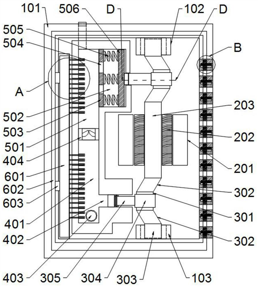
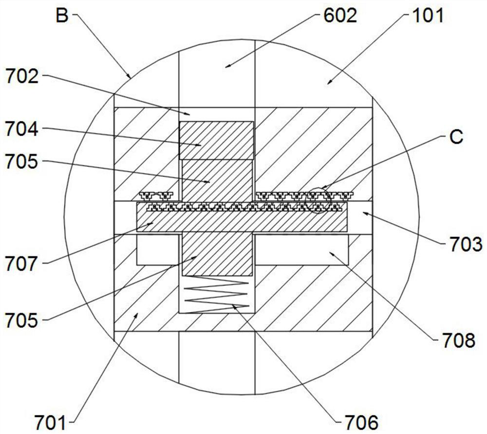
[0027] Rotor superimposed two-stage high-pressure compressor, including support components, power components, transmission components, primary compression components, secondary compression components, expansion drive components, noise reduction and dust-proof components, the support components are located on the outermost side of the whole device to support the compressor The funct...


PUM


Abstract

The invention discloses a rotor stacking dual-stage high pressure compressor. The compressor comprises a support assembly, a power assembly and a transmission assembly, wherein the support assembly islocated on the outermost side of the entire-set device, the power assembly is arranged inside the support assembly, and the side of the power assembly is provided with the transmission assembly. Thecompressor utilizes high-pressure gas continuously updated inside a first-stage compression air tank and a second-stage compression air tank, heat generated by compression is subjected to heat exchange conduction, heat energy of high-pressure air is converted into mechanical energy, so that the energy recycling is realized, heat energy expansion is utilized for driving, so that silencing hole grooves are not blocked by external dust in a non-running state of the compressor, the external dust cannot pass through a heat dissipation through hole to enter the compressor, the compressor has a gooddustproof effect, in a running state of the compressor, the silencing hole grooves which are internally in a grid form and communicate with one another are exposed at the moment, noise of the compressor is reflected and absorbed, and the sound absorption effect is achieved.

Description

technical field [0001] The invention relates to the technical field of compressors, in particular to a rotor superimposed two-stage high-pressure compressor. Background technique [0002] The compressor is a driven fluid machine that converts low-pressure gas into high-pressure gas. It is the heart of the refrigeration system. Existing compressors generate high heat by themselves because of compressed gas, and high heat radiation will affect the surrounding environment of the compressor. , the way of heat dissipation through the heat dissipation groove can carry out heat exchange inside and outside the compressor, and then achieve the heat dissipation effect, but the existence of the heat dissipation groove will also make the interior of the compressor affected by external dust and moisture, and the accumulation of dust will easily block the small parts of the compressor After a long time, it will affect the normal operation of the compressor. The accumulation of moisture wi...

Claims


Application Information

Patent Timeline
Patent Type & Authority Applications(China)
IPC IPC(8): F04B25/00F04B35/04F04B39/06F04B39/00
CPCF04B25/005F04B35/04F04B39/0083F04B39/06
Inventor 方素妍
Owner 山东爱索科技集团有限公司
Why Eureka
Try Eureka