
A multifunctional shaft material feeding device

A multi-functional shaft and feeding technology, applied in metal processing and other directions, can solve the problem of non-adjustable feeding speed, and achieve the effect of satisfying production needs, smooth rotation and quality promotion.

Active Publication Date: 2022-03-22
青岛征和链传动有限公司
View PDF9 Cites 0 Cited by
  • Summary
  • Abstract
  • Description
  • Claims
  • Application Information

AI Technical Summary

Problems solved by technology

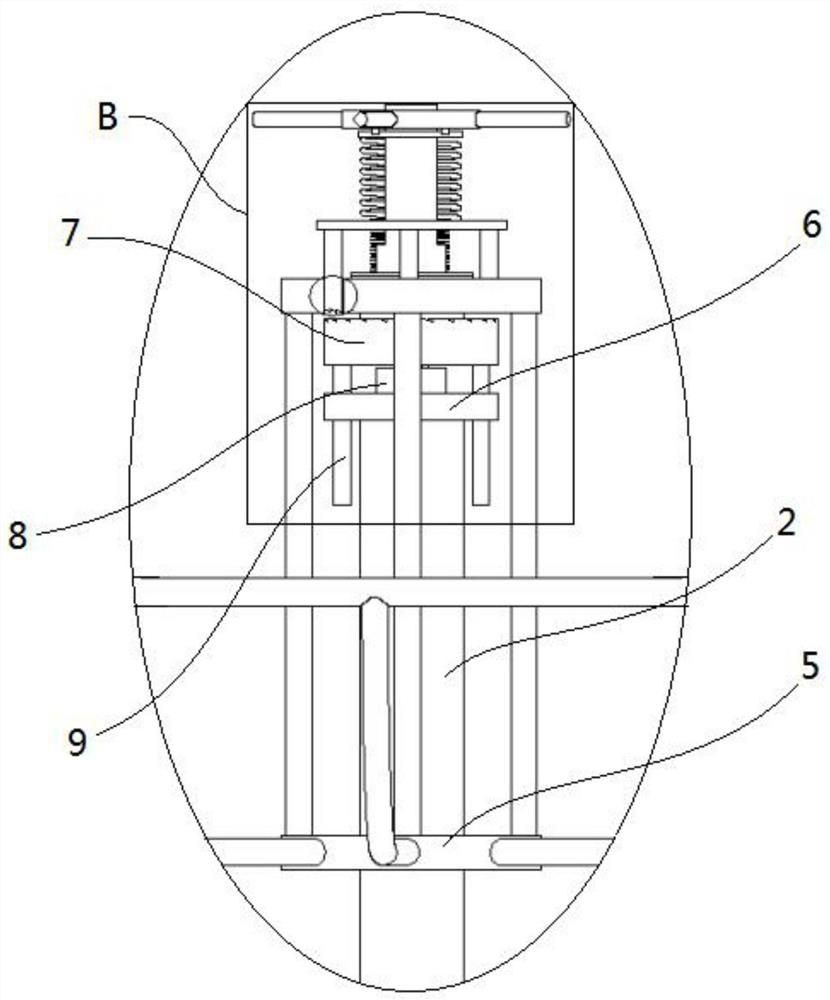
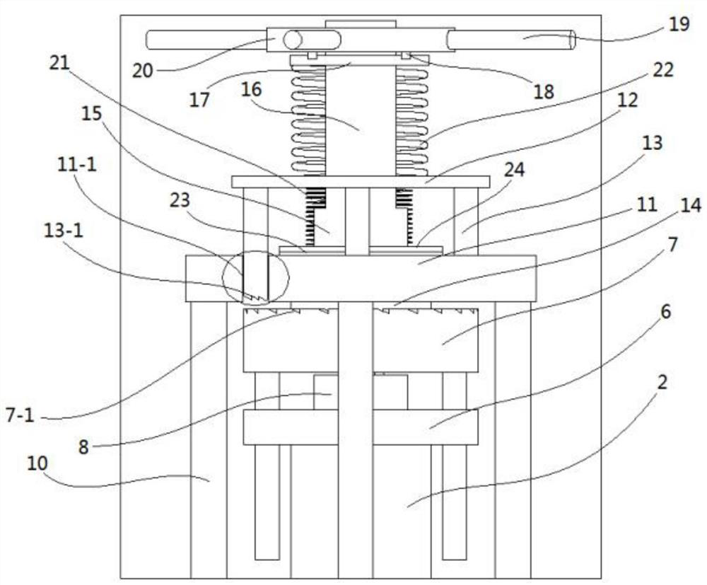
[0006] In order to solve the problems existing in the prior art, the present invention provides a multifunctional shaft material feeding device, which solves the problem that the feeding speed cannot be adjusted, can ensure smooth rotation, and effectively guarantees the processing quality of the pin shaft. At the same time, It can remind the refueling in time during the production and processing, avoid equipment idling, improve work efficiency and reduce labor costs

Method used


Image

  • A multifunctional shaft material feeding device
  • A multifunctional shaft material feeding device
  • A multifunctional shaft material feeding device

Examples


Embodiment Construction

[0031] The following is a detailed description of the implementation of the present invention in a step-by-step manner. This description is only a preferred embodiment of the present invention, and is not used to limit the scope of protection of the present invention. Where the spirit and principles of the present invention Any amendments, equivalent replacements and improvements made within shall be included within the protection scope of the present invention.

[0032] In the description of the present invention, it should be noted that the orientations or positional relationships indicated by the terms "up", "down", "left", "right", "top", "bottom", "inner" and "outer" are based on those shown in the accompanying drawings. Orientation or positional relationship is only for describing the present invention and simplifying the description, rather than indicating or implying that the referred device or element must have a specific orientation, as well as a specific orientation ...


PUM


Abstract

A multi-functional shaft material feeding device, which relates to the technical field of pin shaft processing, includes a disc fixing seat, a main rod vertically arranged at the top of the disc fixing seat, a tray, and a feeding speed adjustment mechanism. The supporting tray is coaxial with the main rod and is connected to the top of the main rod in rotation, and a feeding speed adjustment mechanism is arranged at the center of the supporting tray and above the main rod. The invention solves the problem that the feeding speed of the feeding device cannot be adjusted during the shaft cutting process, effectively improves the quality of the pin shaft, and at the same time, can ensure the smooth rotation of the supporting tray, and can remind the material change in time during the production and processing process, so as to avoid the idling of the equipment , Improve work efficiency and reduce labor costs.

Description

technical field [0001] The invention relates to the technical field of pin shaft processing, in particular to a multifunctional shaft material feeding device. Background technique [0002] During the cutting process of the pin shaft, a feeding device is needed. Most of the existing feeding devices are provided with a rotating tray on the top of a rod, and the twisted shaft material is placed in the tray, and the shaft One end of the material is input into the feed port of the shaft cutter. Although it can meet the basic production needs, it still has the following disadvantages: [0003] 1. The speed of the existing feeding device cannot be adjusted. Since the operating frequency of the shaft cutter is unstable, the speed at which the tray is driven by the shaft material to rotate is not uniform, so that the feeding tray cannot adjust itself according to the operation of the shaft cutter. The speed of the shaft will cause the feeding speed to be too fast or too slow compare...

Claims


Application Information

Patent Timeline
Patent Type & Authority Patents(China)
IPC IPC(8): B23Q7/02
CPCB23Q7/02
Inventor 金玉谟柳全刘振振封璐王晓友金丽君
Owner 青岛征和链传动有限公司
Learn More