Automobile generator rotor inspection mechanism
A technology for automotive generators and rotors, applied in the field of machinery, can solve problems affecting efficiency and cumbersome operation, and achieve the effects of improving measurement accuracy, avoiding interference, and reducing measurement distance
- Summary
- Abstract
- Description
- Claims
- Application Information
AI Technical Summary
Problems solved by technology
Method used
Image
Examples
Embodiment 1
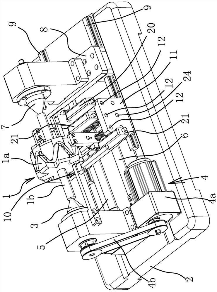
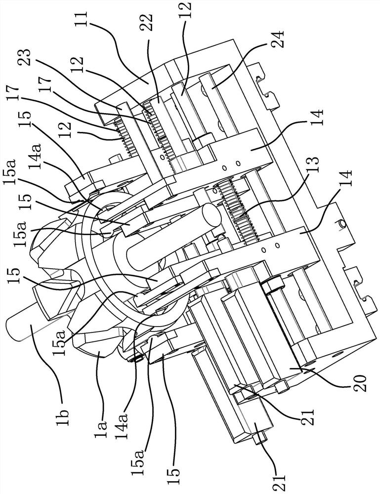
[0029] like figure 1 As shown, the automobile generator rotor includes a ring-shaped claw pole 1a and a shaft body 1b passing through the claw pole 1a. The measuring device for the size of the automobile generator rotor comprises a base 2, a top 3 arranged on the base 2, and a driving source 4 for driving the top 3 to rotate.
[0030] Wherein, the top one 3 is rotatably connected with the base 2, and in this embodiment, the rod part of the top one 3 is rotatably connected with the base 2 through multiple sets of bearings. The driving source 4 includes a motor 4 a fixed on the base 2 and a driving mechanism for connecting the motor 4 a and the top one 3 . In this embodiment, the motor 4a is arranged on one side of the top-3, and the drive mechanism includes a driving wheel fixed on the main shaft of the motor 4a and a driven wheel fixed on the end of the top-3, and the driving wheel and the driven wheel are synchronized by With 4b connection. Naturally, the driving source 4 ...
Embodiment 2
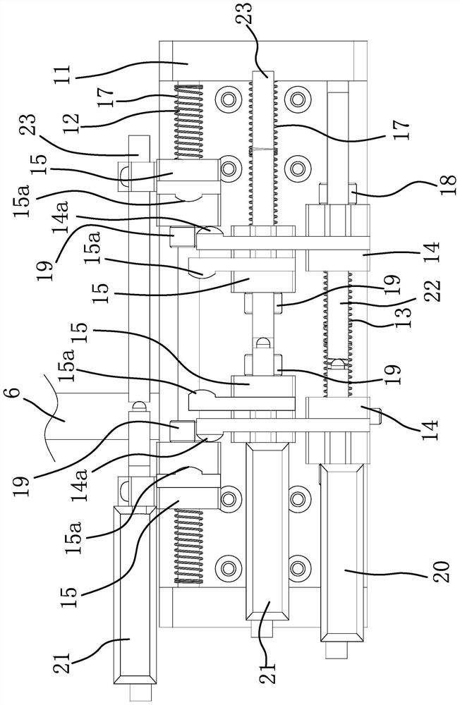
[0047] The structure and principle of this second embodiment are basically the same as that of the first embodiment. The difference is that the position-limiting structure includes a ring body fixed on the corresponding guide rod 12 and a protruding ring formed on the guide rod 12. The base block 14 is located between the protruding ring 1 and the ring body 1, and under the action of the spring 13, the two base blocks 14 press against the ring body 1 and the protruding ring 1 respectively.
Embodiment 3
[0049] The structure and principle of the third embodiment are basically the same as those of the first embodiment, except that the limiting structure 1 includes two protruding rings 2 formed on the corresponding guide rods 12, and the two protruding rings 2 are located on a pair of base blocks 2 15 Between, and under the action of the spring unit, the two base blocks 15 respectively press against the two protruding rings 2.
PUM
 Abstract
Description
Claims
Application Information
 - R&D Engineer
- R&D Manager
- IP Professional
- Industry Leading Data Capabilities
- Powerful AI technology
- Patent DNA Extraction
Browse by: Latest US Patents, China's latest patents, Technical Efficacy Thesaurus, Application Domain, Technology Topic, Popular Technical Reports.
© 2024 PatSnap. All rights reserved.Legal|Privacy policy|Modern Slavery Act Transparency Statement|Sitemap|About US| Contact US: help@patsnap.com


