
Hardware bead threading device

A hardware and bead threading technology, which is applied in the field of hardware bead threading devices, can solve the problems of low work efficiency, waste of manpower, complicated production of parts and assembly costs, etc., and achieve the effect of improving work efficiency and saving labor costs

Pending Publication Date: 2020-11-24
SHENZHEN QIANHAI WELL SELL TECH CO LTD
View PDF1 Cites 4 Cited by
  • Summary
  • Abstract
  • Description
  • Claims
  • Application Information

AI Technical Summary

Problems solved by technology

[0002] The beading of hardware refers to connecting the various components of the hardware equipment in series to form the overall structure of the equipment. For example, in the process of assembling the watch strap, connecting the straps or beads of the watch strap together for assembly is the hardware beading One of them, traditionally, the assembly of belts is often done manually, but this method wastes manpower, low work efficiency, and high cost
[0004] However, in the above-mentioned patents, the structure of the beading device is complicated, the parts are complicated, and the production and assembly costs are relatively high.

Method used


Image

  • Hardware bead threading device
  • Hardware bead threading device

Examples


Embodiment Construction

[0022] In order to make the object, technical solution and advantages of the present invention clearer, the present invention will be further described in detail below in conjunction with the accompanying drawings and embodiments. It should be understood that the specific embodiments described here are only used to explain the present invention, not to limit the present invention.

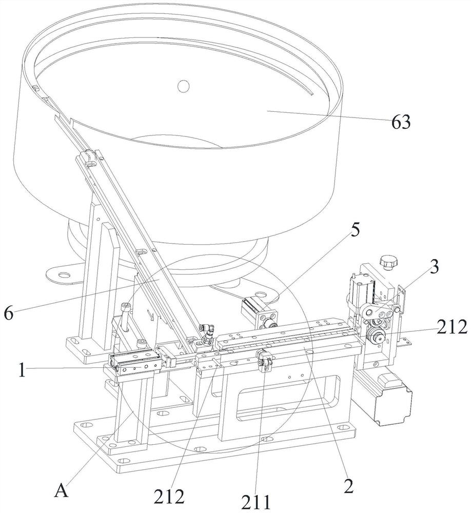
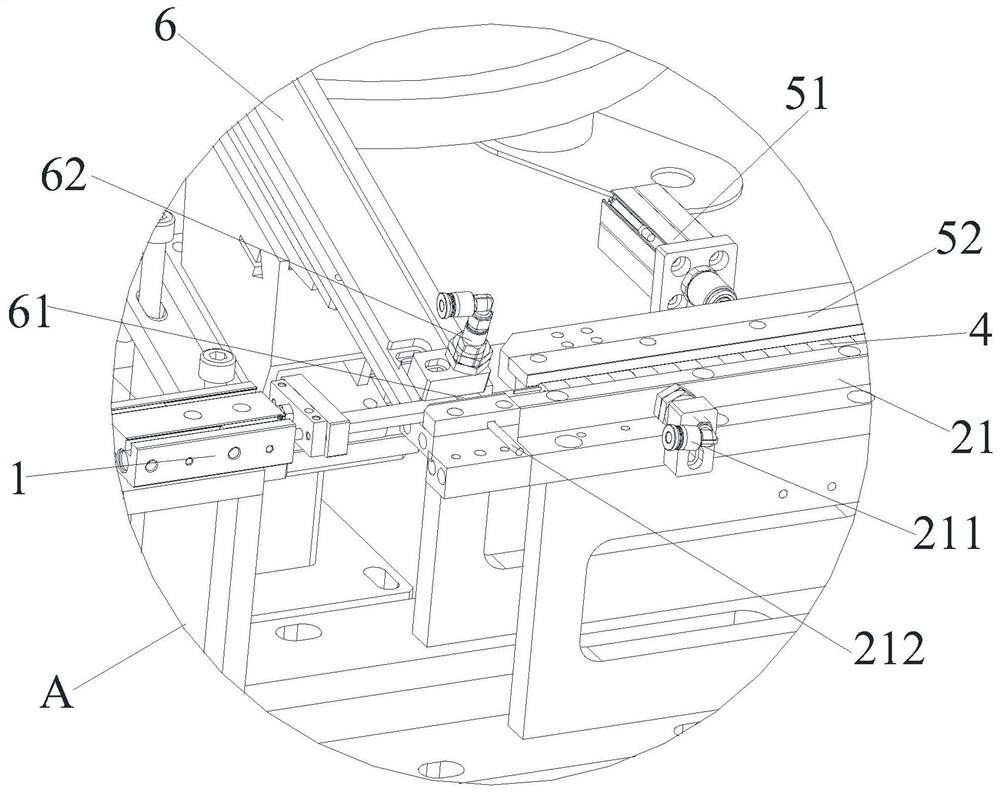
[0023] refer to Figure 1-2 As shown, it is a hardware bead threading device of the present invention, which includes a push mechanism 1, a bead placement position 2 and a wire feeding mechanism 3, and the wire feeding mechanism 3 is arranged opposite to the position of the bead placement position 2. After the pushing mechanism 1 pushes a grain of tape 4 onto the bead placement position 2, the perforations (not shown) of the tape grains 4 have the same direction, and the bead placement position 2 is also provided with a clamping mechanism 5; After the clamping mechanism 5 clamps a grain of tape 4,...


PUM


Abstract

The invention discloses a hardware bead threading device. The hardware bead threading device comprises a pushing mechanism, a bead threading placement position and a wire feeding mechanism, wherein the wire feeding mechanism and the bead threading placement position are oppositely arranged; after the pushing mechanism pushes particles to the bead threading placement position, the perforation directions of the particles are the same; a clamping mechanism is further arranged at the bead threading placement position; after the clamping mechanism clamps the particles, the centers of perforations of the particles are on the same straight line; and the wire feeding mechanism feeds wires, and the wires penetrate through the perforations to connect the particles in series. The bead threading placement position is used for placing the particles to be connected in series; after the pushing mechanism pushes the particles to the bead threading placement position, the perforation directions of theparticles are the same; after the clamping mechanism clamps the particles at the bead threading placement position, the centers of the perforations of the particles at the bead threading placement position are on the same horizontal straight line, so that the wire feeding mechanism can conveniently connect the particles in series after feeding the wires.

Description

technical field [0001] The invention belongs to the technical field of mechanical manufacturing equipment, and in particular relates to a hardware bead threading device. Background technique [0002] The beading of hardware refers to connecting the various components of the hardware equipment in series to form the overall structure of the equipment. For example, in the process of assembling the watch strap, connecting the straps or beads of the watch strap together for assembly is the hardware beading One of them, traditionally, the assembly of the tape is often done manually, but this method wastes manpower, has low work efficiency and high cost. [0003] In order to solve this problem, in the patent No. "CN109531138A", titled "A kind of automatic beading equipment and automatic beading method for stainless steel watch strap parts", a kind of automatic beading equipment for stainless steel watch strap parts is disclosed. rack, control cabinet and two sets of processing sta...

Claims


Application Information

Patent Timeline
IPC IPC(8): B23P19/00B23P21/00
CPCB23P19/001B23P21/00
Inventor 毛平黄伟伟张民智
Owner SHENZHEN QIANHAI WELL SELL TECH CO LTD
Learn More