
A rotary conveying device of a steel cage roll welding machine

A technology of rotary conveying and rolling welding machine, which is applied in the direction of online netting, household appliances, and other household appliances, etc., which can solve the problems of affecting the economic benefits of work, the inability to continue winding welding work, and reducing work efficiency, so as to ensure production efficiency. and work quality, ensuring the economic benefits of work, and improving work efficiency

Active Publication Date: 2021-06-04
江西博展自动化科技有限公司
View PDF8 Cites 0 Cited by
  • Summary
  • Abstract
  • Description
  • Claims
  • Application Information

AI Technical Summary

Problems solved by technology

[0003] For the existing steel cage roll welding machine, when performing the winding welding work of the winding bars, the bundled winding bars are usually placed on the ground, and then passed through the winding bar device to wind on the main bars. In this process, There is no good conveying device for the rebar winding, and when the rebar winding is performed, the rebar winding may appear chaotic, resulting in dead knots, and then the winding welding work cannot be continued, reducing work efficiency and affecting the economic benefits of the work. , the present invention proposes a rotary conveying device of a steel cage roll welding machine to solve the above problems

Method used


Image

  • A rotary conveying device of a steel cage roll welding machine
  • A rotary conveying device of a steel cage roll welding machine
  • A rotary conveying device of a steel cage roll welding machine

Examples


Embodiment Construction

[0029] The technical solutions in the embodiments of the present invention will be clearly and completely described below. The embodiments of the present invention and all other embodiments obtained by persons of ordinary skill in the art without making creative efforts belong to the protection scope of the present invention.

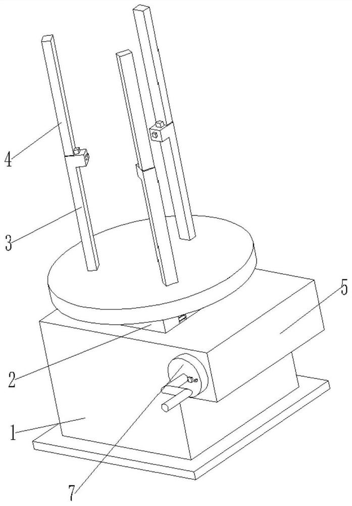
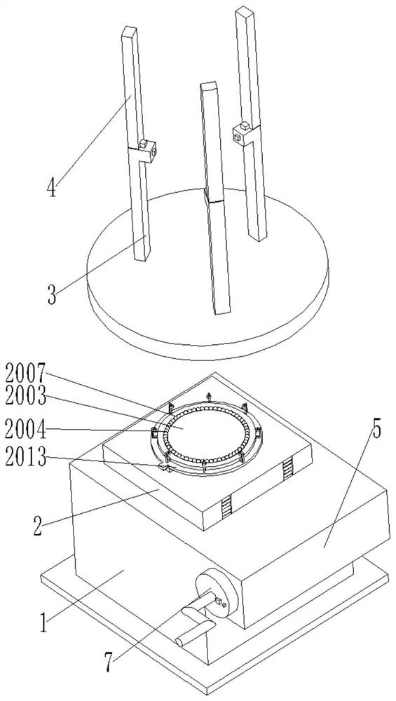
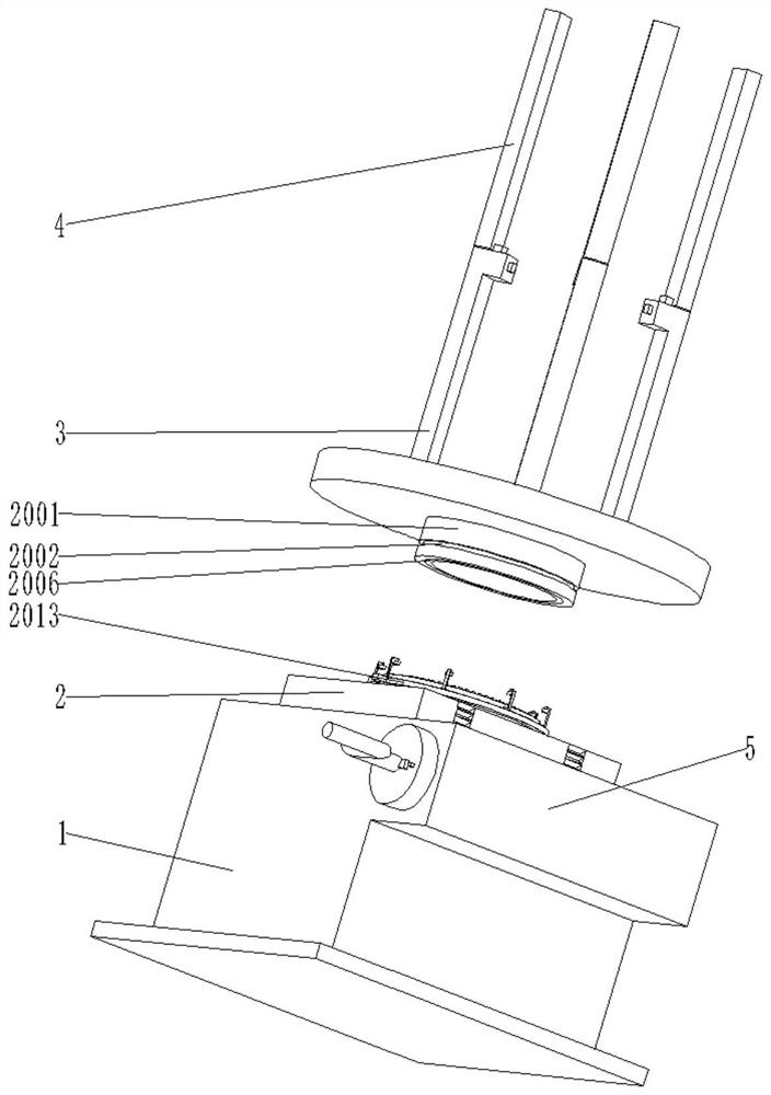
[0030] see figure see Figure 1 to Figure 10 , the present invention provides a technical solution: a rotary conveying device for a steel cage roll welding machine, including a base 1, a telescopic body 2, a first support rod 3, a second support rod 4, a transmission structure 6, and a rotation mechanism 20;

[0031] A telescopic body 2 is movable in the base 1, a support disc is provided on the telescopic body 2, a first support rod 3 is equidistantly arranged on the support disc, and a second support rod 4 is connected to the first support rod 3, and One side of the base 1 is integrally formed with a placement box 5;

[0032] The placement box 5 is ...


PUM


Abstract

The invention discloses a rotary conveying device of a steel cage roll welding machine. With the rotating mechanism provided in the present invention, when the roll welder performs welding work around the bar, the function of rotating and transporting the around bar can be performed, so that the transport of the around bar The work is smoother, ensuring the normal progress of the welding work around the rebar, and through the set of detachable first support rod and second support rod, it is more convenient to place the rebar and provide convenience for the staff. The bottom end of the mechanism is connected with the telescopic body, the base and the transmission structure, so that the position and height of the winding ring can be adjusted to ensure that it is at a suitable height position, which provides convenience for the welding work of the winding and avoids welding during the winding process. In the process, with the reduction of the number of coils, the position of the coils will be lowered, thereby improving work efficiency and ensuring the economic benefits of production and processing.

Description

technical field [0001] The invention relates to the technical field of seam welder equipment, in particular to a rotary conveying device of a steel cage seam welder. Background technique [0002] CNC steel cage roll welding machine is a kind of equipment controlled by PLC to process and produce steel cages; the appearance of CNC steel cage roll welding machine has ended the history of manual binding of steel cages, and has improved the efficiency of bridge and high-speed rail manufacturing in my country. According to the construction requirements, the main reinforcement of the reinforcement cage is fixed by manually passing through the corresponding template round hole of the fixed rotating disk to the corresponding hole of the moving rotating disk. The rotating disk and the moving rotating disk rotate to wrap the rebar on the main reinforcement (the moving disk moves backward while rotating), and weld at the same time to form a product reinforcement cage --- it is a drilled p...

Claims


Application Information

Patent Timeline
Patent Type & Authority Patents(China)
IPC IPC(8): B21F27/20B21F23/00
CPCB21F23/00B21F27/20
Inventor 姚超坤
Owner 江西博展自动化科技有限公司
Learn More