
Display panel brightness compensation control method and brightness compensation control system

A display panel and brightness compensation technology, which is applied to static indicators, cathode ray tube indicators, instruments, etc., can solve the problems of inconsistent brightness of OLED devices, inconsistent brightness of display panels, uneven display pictures, etc., and save data storage space , Improve uneven brightness, improve the effect of consistency

Inactive Publication Date: 2020-11-20
KUNSHAN GO VISIONOX OPTO ELECTRONICS CO LTD
View PDF20 Cites 9 Cited by
  • Summary
  • Abstract
  • Description
  • Claims
  • Application Information

AI Technical Summary

Problems solved by technology

Due to the voltage drop of the power supply voltage affected by the impedance of the power supply wiring during the transmission process, the current flowing through each driving circuit is different, resulting in inconsistencies in the brightness of the OLED devices in each area
When the display panel displays a solid color picture, the brightness of each area of ​​the display panel will be inconsistent, and the display picture will be uneven.

Method used


Image

  • Display panel brightness compensation control method and brightness compensation control system
  • Display panel brightness compensation control method and brightness compensation control system
  • Display panel brightness compensation control method and brightness compensation control system

Examples


Embodiment Construction

[0036] The technical solutions in the embodiments of the present application will be clearly and completely described below in conjunction with the drawings in the embodiments of the present application. It should be understood that the specific embodiments described here are only used to explain the present application, but not to limit the present application. In addition, it should be noted that, for the convenience of description, only some structures related to the present application are shown in the drawings but not all structures. Based on the embodiments in this application, all other embodiments obtained by persons of ordinary skill in the art without creative efforts fall within the protection scope of this application.

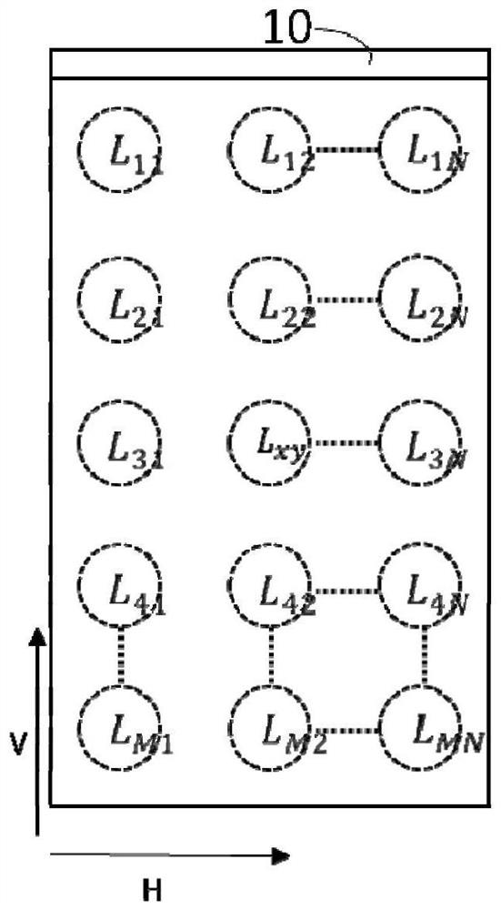
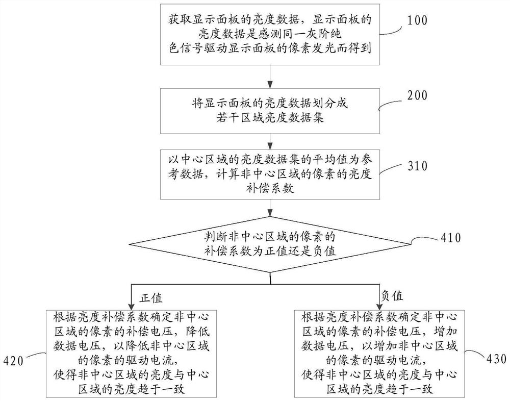
[0037] Such as figure 1 As shown, the embodiment of the present application provides a display panel brightness compensation control method, including:

[0038] Step 100: Obtain luminance data of the display panel. The luminance data of the displ...


PUM


Abstract

The invention relates to the technical field of display, in particular to a display panel brightness compensation control method and a display panel brightness compensation control system. The displaypanel brightness compensation control method comprises the steps of: acquiring brightness data of a display panel, wherein the brightness data of the display panel is obtain through sensing the samegray-scale pure color signal driving pixels of the display panel to emit light; dividing the brightness data of the display panel into a plurality of regional brightness data sets, and dividing the brightness data of the display panel according to a plurality of light-emitting regions of the display panel, wherein the plurality of regional brightness data sets comprise a brightness data set located in a central region of the display panel and a brightness data set located in a non-central region of the display panel; taking the brightness data set of the central region as reference data, and calculating a brightness compensation coefficient of the pixels of the non-central region; and adjusting a compensation voltage of the pixels in the non-central region through using the brightness compensation coefficient, so that the display panel emits light uniformly. According to the display panel brightness compensation control method, the data storage space can be saved, the operation rate isincreased, and the uniformity of the brightness of the display panel is improved.

Description

technical field [0001] The present application relates to the field of display technology, in particular to a brightness compensation control method and a brightness compensation control system of a display panel. Background technique [0002] Organic light emitting diode (Organic Light Emitting Display, OLED) display panel has self-illumination, low driving voltage, high luminous efficiency, short response time, high definition and contrast, wide operating temperature range, and can realize flexible display and large-area full-color display And many other advantages, it is recognized by the industry as the display panel with the most development potential. [0003] For an OLED display panel, each pixel includes an OLED device and a driving circuit for driving the OLED device to emit light. Since the power supply voltage is affected by the impedance of the power supply wiring during the transmission process, a voltage drop occurs, so that the current flowing through each dr...

Claims


Application Information

Patent Timeline
IPC IPC(8): G09G3/3233G09G5/10
CPCG09G3/3233G09G5/10G09G2320/0233
Inventor 韩冲
Owner KUNSHAN GO VISIONOX OPTO ELECTRONICS CO LTD
Learn More