
Display panel and electronic equipment

A display panel and display area technology, which is applied in the direction of TV, electrical components, color TV, etc., can solve the problems affecting the mechanical strength and product yield of the panel, increasing the complexity of the process and the production cost, etc.

Active Publication Date: 2020-11-20
XIAMEN TIANMA MICRO ELECTRONICS
View PDF4 Cites 2 Cited by
  • Summary
  • Abstract
  • Description
  • Claims
  • Application Information

AI Technical Summary

Problems solved by technology

The conventional design scheme needs to set an opening for image acquisition in the display panel. The opening design not only increases the complexity and production cost of the process, but also affects the mechanical strength of the panel and the product yield.

Method used


Image

  • Display panel and electronic equipment
  • Display panel and electronic equipment
  • Display panel and electronic equipment

Examples


Embodiment Construction

[0042] The embodiments of the present invention will be clearly and completely described below in conjunction with the accompanying drawings in the embodiments of the present invention. Obviously, the described embodiments are only some of the embodiments of the present invention, not all of them. Based on the embodiments of the present invention, all other embodiments obtained by persons of ordinary skill in the art without making creative efforts belong to the protection scope of the present invention.

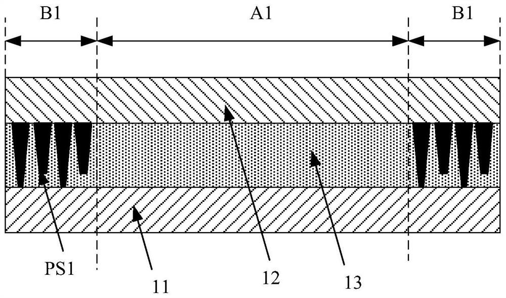
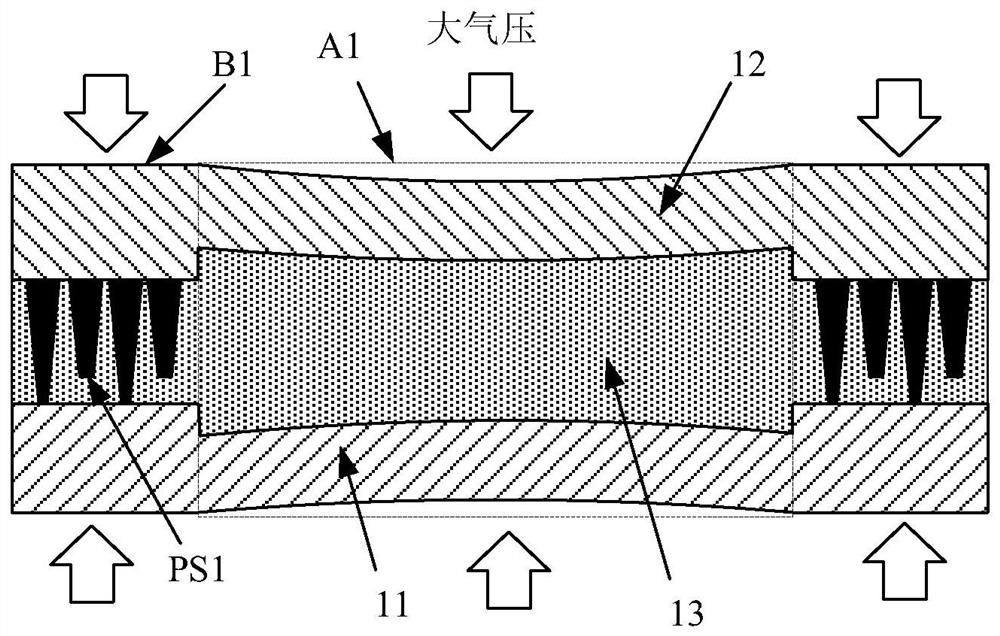
[0043] like figure 1 as shown, figure 1 It is a structural schematic diagram of a conventional liquid crystal panel with a blind hole area. The liquid crystal display panel includes an array substrate 11 and a color filter substrate 12 disposed opposite to each other, and a liquid crystal layer 13 between them. The liquid crystal display panel has a blind hole area A1 and a display area B1 surrounding the blind hole area A1. In the liquid crystal display panel, in order to...


PUM


Abstract

The invention discloses a display panel and electronic equipment. The display panel is provided with a display area and a blind hole area. The display panel comprises an array substrate and a color film substrate which are oppositely arranged; a liquid crystal layer is positioned between the array substrate and the color film substrate; the array substrate is provided with a plurality of pixel units, wherein the pixel units are located in the display area, and the vertical projections of the pixel units on the array substrate are not overlapped with the vertical projections of the blind hole area on the array substrate; and the blind hole area is provided with a driving electrode, and the driving electrode is used for controlling deflection of liquid crystal molecules in the blind hole area. The display panel is provided with the driving electrode in the blind area, and liquid crystal molecules in the blind hole area can be controlled to deflect through the driving electrode, so that the refractive index of the liquid crystal layer in the blind hole area is adjusted, and the optical path difference of the blind hole area is reduced or even eliminated.

Description

technical field [0001] The present invention relates to the technical field of electronic equipment, and more specifically, to a display panel and electronic equipment. Background technique [0002] With the continuous development of science and technology, more and more electronic devices with display functions are widely used in people's daily life and work, which brings great convenience to people's daily life and work, and has become an indispensable essential tool. An important part of an electronic device to realize a display function is a display panel, and a liquid crystal display panel is one of the current mainstream display panels. [0003] Electronic equipment needs to integrate a camera to realize the image acquisition function. Conventional design schemes require an opening for image acquisition to be provided in the display panel. The opening design not only increases the complexity and manufacturing cost of the process, but also affects the mechanical stren...

Claims


Application Information

Patent Timeline
Patent Type & Authority Applications(China)
IPC IPC(8): G02F1/1343G02F1/1335H04N5/225
CPCG02F1/134309G02F1/133514H04N23/57
Inventor 郭单余姚淑琳颜华生谢玉练周婷
Owner XIAMEN TIANMA MICRO ELECTRONICS
Learn More