Novel box type pneumatic actuator

A pneumatic actuator, box-type technology, applied in the direction of engine components, mechanical equipment, fluid pressure actuators, etc., can solve the problems of inconvenience, low cost, no take out, etc., and achieve high adjustment accuracy, convenient maintenance, and easy operation Effect

Inactive Publication Date: 2020-11-20
NINGBO FUSHIDA ELECTRIC ENG
View PDF8 Cites 0 Cited by
  • Summary
  • Abstract
  • Description
  • Claims
  • Application Information

AI Technical Summary

Problems solved by technology

The existing positioner has two major defects: on the one hand, because the existing positioner uses a mechanical positioner, the control characteristic is non-linear, which leads to the unsatisfactory adjustment accuracy of the positioner, and the difficulty of debugging the positioner is relatively high. On the other hand, the positioner is installed in the cabinet or the cabinet, and the cabinet is usually a sealed mechanism without ventilation function, which leads to poor heat dissipation effect of the positioner and high failure rate of precision electronic components, so it will need to be repaired The locator is often maintained, which is very inconvenient
However, the cost of such a box is not low when it is manufactured, and its practical value is not large.
Moreover, the case did not come up with a useful solution for the problem that the locator is prone to heat.

Method used


Image

  • Novel box type pneumatic actuator
  • Novel box type pneumatic actuator

Examples


Embodiment Construction

[0029] Below in conjunction with accompanying drawing and specific embodiment the present invention is described in further detail:

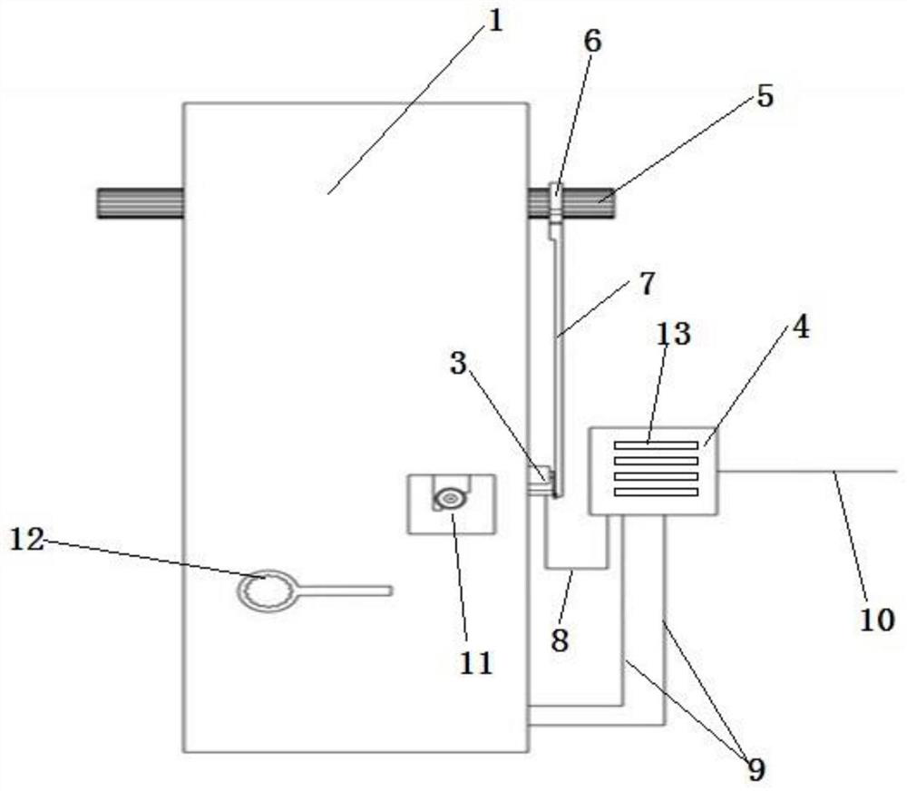
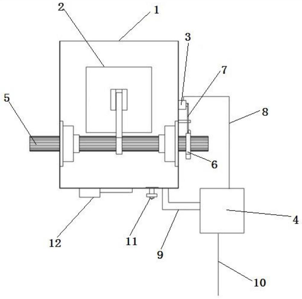
[0030] like figure 1 , figure 2 As shown, a new box-type pneumatic actuator includes a box body 1, a cylinder 2 located inside the box body 1, a signal feedback device 3 fixed on the outer wall of the box body 1, and a positioner 4 arranged outside the box body 1, The inside of the box 1 is provided with a horizontal horizontal spindle 5 connected to the cylinder 2 adjacent to its top. One end of the device 4 is provided with a universal joint 6, and a universal joint connecting rod 7 is arranged below the universal joint 6, and the universal joint 6 is connected with the signal feedback device 3 through the universal joint connecting rod 7, and the signal feedback device A signal cable 8 is provided between 3 and the positioner 4, and a signal gas source pipeline 9 is provided between the positioner 4 and the cylinder 2. The side of the pos...


PUM


Abstract

The invention discloses a pneumatic actuator, and aims to provide a novel box type pneumatic actuator which is simple in structure and convenient to repair, enables a locator to be timely subjected toheat dissipation and is high in adjustment accuracy. The novel box type pneumatic actuator comprises a box body, an air cylinder, a signal feedback device and the locator. The air cylinder is locatedinside the box body, the signal feedback device is fixed to the outer side wall of the box body, and the locator is arranged on the outer side of the box body. A main shaft which is horizontally arranged and connected with the air cylinder is arranged on the portion, adjacent to the top of the box body, of the interior of the box body, and the two ends of the main shaft are exposed out of the side wall of the box body and located on the two sides of the box body correspondingly. A universal joint is arranged at the end, close to the locator, of the main shaft, and a universal joint connectingrod which is used for being connected with the signal feedback device is arranged at the bottom of the universal joint. A signal cable is arranged between the signal feedback device and the locator,and signal air source pipelines are arranged between the locator and the air cylinder. By the adoption of the design, the locator can be timely subjected to heat dissipation in the working process, and the effect of accurately controlling the air cylinder can be achieved according to the signal feedback device.

Description

technical field [0001] The invention relates to the technical field of smoke duct baffle control, in particular to a novel box-type pneumatic actuator. Background technique [0002] The opening and closing of the baffle inside the flue duct is generally controlled by a pneumatic actuator, which includes a positioner for assisting in adjusting the position of the baffle. The existing positioner has two major defects: on the one hand, because the existing positioner uses a mechanical positioner, the control characteristic is non-linear, which leads to the unsatisfactory adjustment accuracy of the positioner, and the difficulty of debugging the positioner is relatively high. On the other hand, the positioner is installed in the cabinet or the cabinet, and the cabinet is usually a sealing mechanism without ventilation function, which leads to poor heat dissipation effect of the positioner and high failure rate of precision electronic components, so it will need to be repaired T...

Claims


Application Information

Patent Timeline
IPC IPC(8): F16K31/12F16K31/14F16K37/00F15B21/08
CPCF15B21/08F16K31/12F16K31/14F16K37/0083
Inventor 衣启坤林韬付德庆屠尹雄
Owner NINGBO FUSHIDA ELECTRIC ENG
Why Eureka
Try Eureka