
Automatic steel wire threading device

An automatic threading and steel wire technology, applied in textiles and papermaking, weft knitting, knitting, etc., can solve the problems that the steel wire cannot be threaded in place, the steel wire cannot be fully tightened, and the pressure wheel is easy to loosen, etc.

Pending Publication Date: 2020-11-20
JIANGSU JINLONG TECHNOLOGY CO LTD
View PDF0 Cites 0 Cited by
  • Summary
  • Abstract
  • Description
  • Claims
  • Application Information

AI Technical Summary

Problems solved by technology

[0002] The existing flat knitting machine needs to be equipped with a steel wire structure. The steel wire is driven through the steel wire structure to pass through the corresponding through hole of the wire plate. The steel wire is pre-wound on the winding wheel, and then the motor drives the winding wheel to rotate forward or reverse to drive the steel wire. Compared with the through hole of the wire threading plate for threading or taking up the wire, in the actual use process, because the winding wheel is driven by the motor to rotate, when the steel wire is threading or taking up the wire, the winding wheel will rotate, and the steel wire will The locking device is only realized by a set of pressure wheels, which are easy to loosen, which makes the whole steel wire not fully tightened, makes the steel wire and the winding wheel relatively slip, and makes the steel wire cannot be threaded in place or The winding is in place, and the stability and reliability of the winding and threading cannot be guaranteed

Method used


Image

  • Automatic steel wire threading device
  • Automatic steel wire threading device
  • Automatic steel wire threading device

Examples


Embodiment Construction

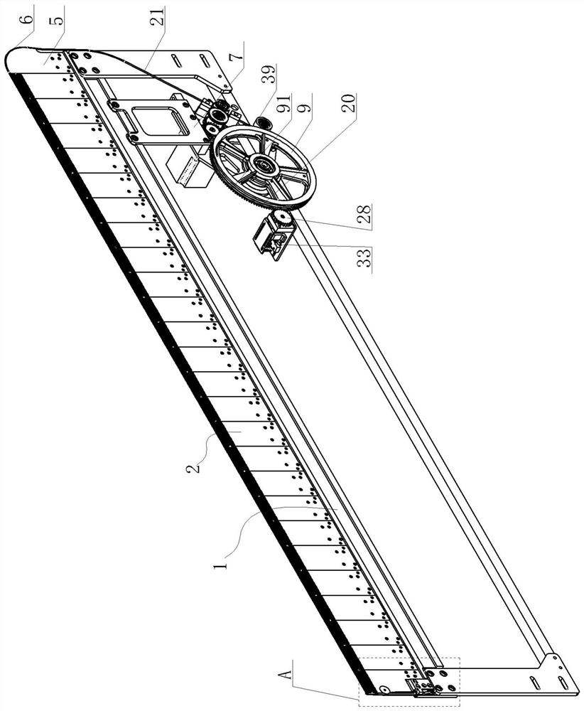
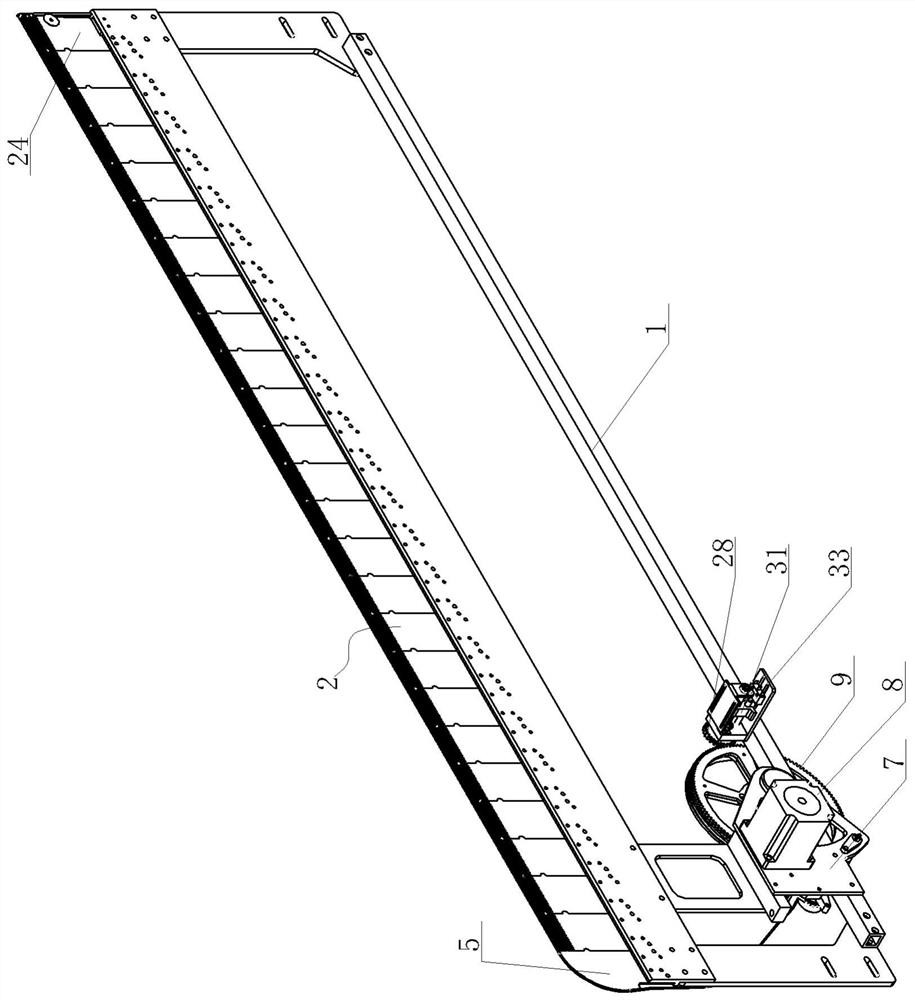
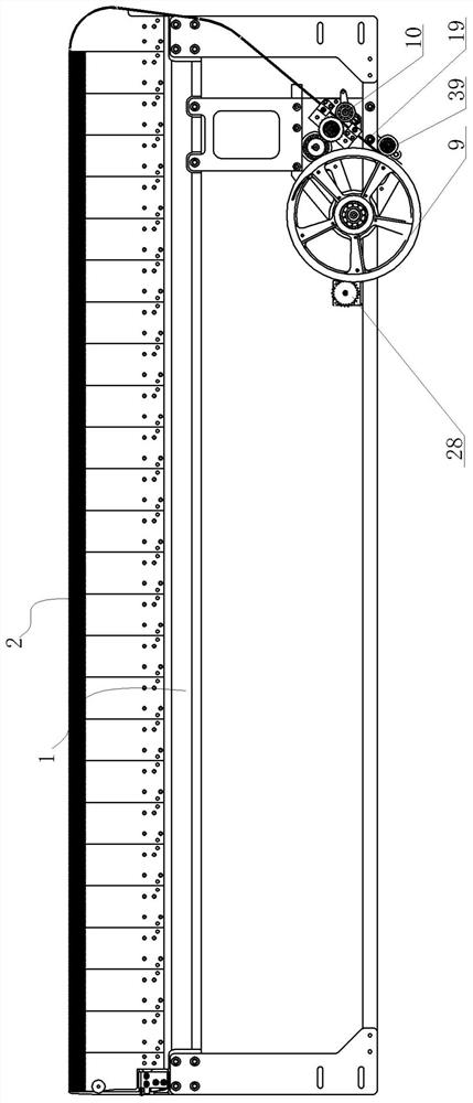
[0023] Automatic wire threading device, see Figure 1-Figure 9 : it comprises a frame 1, a group of threading plates 2 are arranged on the upper beam of the frame 1, threading needles 3 of the threading plate 2 are provided with through threading holes 4, and the threading holes 4 of all threading needles 3 The holes 4 are arranged in a straight line, and one side of the upper cross beam of the frame 1 is provided with a guiding wire threading plate 5, and the outer periphery of the guiding threading plate 5 is provided with a guiding line 6, and the frame 1 corresponds to the guiding threading plate 5. The lower area is provided with a driving mounting frame 7, and the driving mounting frame 7 is provided with a driving motor 8, a take-up wheel 9, and a line pressing roller 10. The output end of the driving motor 8 is connected with a transmission shaft 11, and the transmission shaft 11 is set with The first one-way bearing 12, the second one-way bearing 13, the active rotati...


PUM


Abstract

The invention provides an automatic steel wire threading device. Stable and reliable actions of wire retracting and threading are ensured as a motor unidirectionally drives a wire retracting gear anda wire threading gear to act in a wire threading process, so that the stable and reliable operation of a flat knitting machine is guaranteed. The automatic steel wire threading device comprises a rack. A group of wire threading plates are arranged on an upper cross beam of the rack, perforated wire threading holes are formed in wire threading needles of the wire threading plates, the wire threading holes of all the wire threading needles are formed linearly, a guiding wire threading plate is arranged on one side of the upper cross beam of the rack, a guiding wire channel is arranged on the periphery of the guiding wire threading plate, a driving mounting rack is arranged in a lower area, corresponding to the guiding wire threading plate, of the rack, a driving motor, a wire retracting wheel and a wire compacting roller are arranged on the driving mounting rack, a transmission shaft is connected to an output end of the driving motor, a first unidirectional bearing and a second unidirectional bearing are arranged on the transmission shaft in a sleeving manner, and the first unidirectional bearing and the second unidirectional bearing are opposite in driving rotating direction.

Description

technical field [0001] The invention relates to the technical field of flat knitting machine structures, in particular to an automatic steel wire threading device. Background technique [0002] The existing flat knitting machine needs to be equipped with a steel wire structure. The steel wire is driven through the steel wire structure to pass through the corresponding through hole of the wire plate. The steel wire is pre-wound on the winding wheel, and then the motor drives the winding wheel to rotate forward or reverse to drive the steel wire. Compared with the through hole of the wire threading plate for threading or taking up the wire, in the actual use process, because the winding wheel is driven by the motor to rotate, when the steel wire is threading or taking up the wire, the winding wheel will rotate, and the steel wire will The locking device is only realized by a set of pressure wheels, which are easy to loosen, which makes the whole steel wire not fully tightened,...

Claims


Application Information

Patent Timeline
IPC IPC(8): D04B15/00
CPCD04B15/00
Inventor 金永良张和中侯英杰邱屹
Owner JIANGSU JINLONG TECHNOLOGY CO LTD
Learn More