
Flywheel shell casting mould used for engine casting

A technology for casting molds and flywheel shells, which is applied in the field of casting molds for flywheel shells, can solve the problems of unfavorable and rapid disassembly of injection molding parts, insufficient functions of disassembling casting parts, and lack of selective cooling, and achieves convenient and flexible demoulding and good demoulding effect. , the effect of casting convenience

Inactive Publication Date: 2020-11-20
叶智尚
View PDF11 Cites 0 Cited by
  • Summary
  • Abstract
  • Description
  • Claims
  • Application Information

AI Technical Summary

Problems solved by technology

[0007] The purpose of the present invention is to provide a flywheel shell casting mold for engine casting, to solve the problem that the currently used mold casting proposed in the above background technology is mainly used for shaping processing, and the function of disassembling the casting is insufficient, and the phenomenon of staining is prone to occur. It is not conducive to quick disassembly of injection molded parts, and it does not have a selective cooling function. After injection molding, it is not possible to quickly choose to cool down the mold

Method used


Image

  • Flywheel shell casting mould used for engine casting
  • Flywheel shell casting mould used for engine casting
  • Flywheel shell casting mould used for engine casting

Examples


Embodiment Construction

[0030] The following will clearly and completely describe the technical solutions in the embodiments of the present invention with reference to the accompanying drawings in the embodiments of the present invention. Obviously, the described embodiments are only some, not all, embodiments of the present invention.

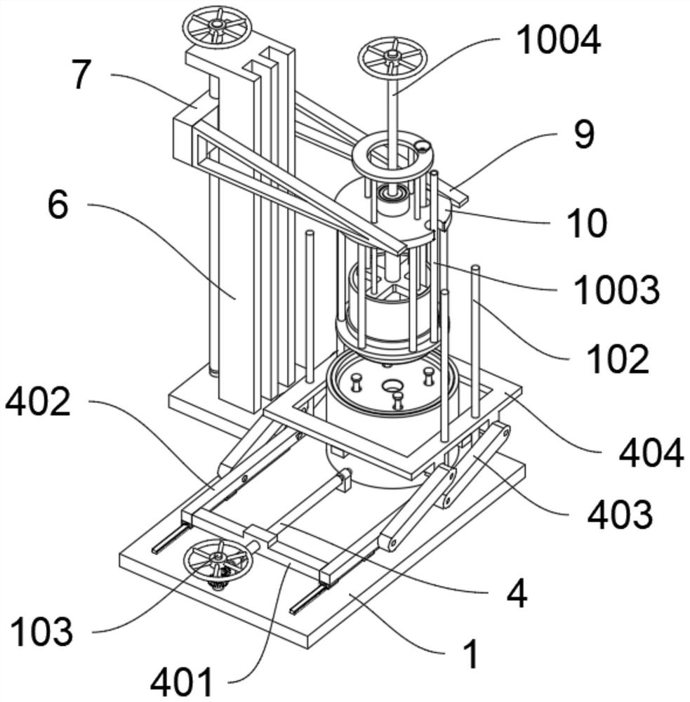
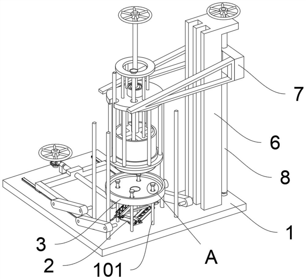
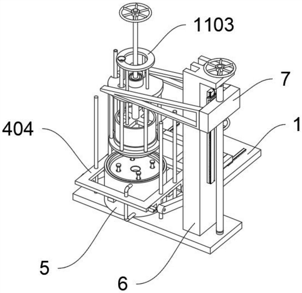
[0031] see Figure 1 to Figure 8 , an embodiment provided by the present invention: a casting mold for a flywheel housing for engine casting, including a base 1; the base 1 also includes a push rod 101; The tops of the rods 101 are all tapered and trapezoidal structures; wherein, the base 1 also includes a guide rod A102 and a handwheel shaft 103; four sets of guide rods A102 are fixedly arranged on the front side of the base 1; Cylinder structure, the bearing is fixedly installed in the cylinder structure through interference fit, and the handwheel shaft 103 is fixedly arranged in the middle of the bearing through interference fit, and the handwheel shaft 103 is con...


PUM


Abstract

The invention discloses a flywheel shell casting mould used for engine casting and relates to the technical field of car moulds. The flywheel shell casting mould solves the problems that casting of amould used at present is mainly used for shaping machining, the function of disassembling a casting part is insufficient, the phenomenon of material sticking occurs easily, and an injection molding part cannot be disassembled beneficially and rapidly. The flywheel shell casting mould used for engine casting comprises a base. The base further comprises ejection rods. Four ejection rods are fixedlyarranged on the front side of the base. The top of each ejection rod is of a cone trapezoidal structure. A screw jack is fixedly arranged on the top of the front side of the base. A bottom mould bodyis fixedly arranged on the top of the screw jack. According to the flywheel shell casting mould, by arranging the ejection rods and the cone trapezoidal hole, the function of convenient bottom demoulding is provided for the mould, by means of the ejection rods, the casting part can be supported, and the bottom mould can directly fall off. Compared with an integrated type mould commonly used at present, demoulding is more convenient and flexible, the demoulding effect is better, and the phenomena that materials are bonded to a flywheel shell, and the mould gets stuck can be effectively prevented.

Description

technical field [0001] The invention relates to the technical field of automobile molds, in particular to a casting mold for a flywheel housing used for engine casting. Background technique [0002] The engine flywheel housing casting mold is a casting mold provided for the production of the engine flywheel housing, which requires manual operation, but the current casting molds for the engine flywheel housing have low safety performance and cause harm to the staff. [0003] After searching, for example, the patent No. CN110328335A discloses a mold for casting flywheels with shell mold and shell core technology, which includes a plurality of shells made of molding sand and stacked together up and down. The shells include an upper shell and a lower shell. The shell, the lower shell of the upper shell and the upper shell of the lower shell are provided with interconnected inrunners, the inrunner and the cavity of the upper shell and The cavity of the lower shell is connected, ...

Claims


Application Information

Patent Timeline
IPC IPC(8): B22C9/06B22C9/28B22D29/04B22D30/00
CPCB22C9/06B22C9/065B22C9/28B22D29/04B22D30/00
Inventor 叶智尚
Owner 叶智尚
Learn More