A blow bar with dual functions of striking and extruding

A dual-function blow bar technology, applied in grain processing, etc., can solve the problems of resource waste, wear-resistant block damage, and low production efficiency, and achieve good economic benefits, small discharge fineness, and long service life.

Active Publication Date: 2021-07-27
ZHENGZHOU UNIV
View PDF6 Cites 0 Cited by
  • Summary
  • Abstract
  • Description
  • Claims
  • Application Information

AI Technical Summary

Problems solved by technology

[0006] 1) The blow bar only has the function of hitting and crushing the material. After repeated hitting for many times, it may still not be able to reach the final particle size required. low efficiency
[0007] 2) In the entire structure of the blow bar, the wear-resistant surface cannot move relatively, causing the damaged part of the blow bar surface to always be at almost the same position, even if the striking surface is spliced ​​by multiple wear-resistant blocks, the damaged There is always a wear-resistant block in a fixed position, and the damaged wear-resistant block is partially damaged instead of a whole piece, and replacement causes waste of resources; while the working object of the blow bar is a material of different material, shape, and particle size. It is impossible to determine the specific location where the blow bar is vulnerable to damage during design, and it is also impossible to strengthen it in a targeted manner during manufacture
The entire crushing equipment has undergone major changes, but there is no more innovation in the technical solution of the hammer head. During the working process, the function of the rotary hammer and the fixed hammer (or movable hammer) rotating in opposite directions to squeeze the material cannot be completed.

Method used


Image

  • A blow bar with dual functions of striking and extruding
  • A blow bar with dual functions of striking and extruding
  • A blow bar with dual functions of striking and extruding

Examples


Embodiment Construction

[0059] The technical solution of the present invention will be further described in detail below in conjunction with the accompanying drawings, but the protection scope of the present invention is not limited to the following description. In the description of the present invention, unless otherwise specified, the orientations or positional relationships indicated by the terms "upper", "lower", "inner", "outer", "left", "right" etc. are based on those shown in the accompanying drawings Orientation or positional relationship is only for the convenience of describing the present invention and simplifying the description, and does not indicate or imply that the referred device or element must have a specific orientation, be constructed and operated in a specific orientation, and thus should not be construed as a limitation of the present invention.

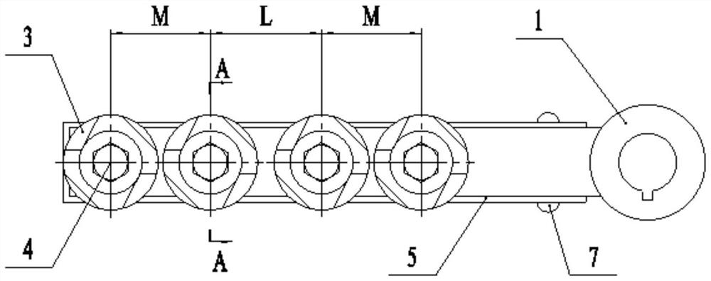
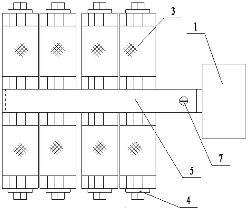
[0060] like Figure 1 to Figure 23 As shown, a blow bar with dual functions of impact and extrusion includes a hammer handle 1, a h...


PUM


Abstract

The invention belongs to the technical field of crushing equipment, and relates to a blow bar with dual functions of striking and squeezing, including a hammer handle, a hammer shaft, a rotary hammer, hexagon flange bolts, a U-shaped sheath, a positioning screw and a fixing screw. There is a shaft hole on the hammer handle, and the hammer shaft is installed with interference in the shaft hole, and the rotary hammer is installed on the hammer shaft, and the U-shaped sheath protects the hammer handle. The hammer handle of the blow bar of the invention is made of low-alloy high-strength steel, which has high strength and high toughness, and the rotary hammer is made of high-manganese steel, which has good wear resistance. When working, the rotary hammer rotates under the impact of the material, which increases the striking area and high efficiency of striking the material; the section of the rotary hammer is a ring and a four-leaf clover-like structure, and the four-leaf clover-like structure will rotate under the impact of the material The driving force makes the rotary hammer squeeze some materials, which increases the use function of the blow bar, and the fineness of the output is small, which improves the service cycle of the blow bar and has good economic benefits. The invention is an innovation in the design and manufacture of the blow bar.

Description

technical field [0001] The invention belongs to the technical field of crushing equipment, and in particular relates to a blow bar with dual functions of striking and squeezing. Background technique [0002] In mining, smelting, building materials and many other fields, a large amount of raw materials and reused waste need to be processed by crushers every year. The impact crusher has the advantages of simple structure, large crushing ratio, low energy consumption, high output, light weight, etc. It is widely used in various ore crushing, railway, highway, energy, cement, chemical, construction and other industries. [0003] The impact crusher is a machine that crushes materials by repeated impacts. The blow bar is fixedly installed on the high-speed rotating rotor, and several counter-attack blow bars are arranged at different angles along the crushing cavity. When the material enters the action area of ​​the blow bar, it is first crushed by the first impact of the blow b...

Claims


Application Information

Patent Timeline
Patent Type & Authority Patents(China)
IPC IPC(8): B02C13/28
CPCB02C13/28
Inventor 刘胜新陈永潘继民马贺祥吴书菲王靖博付雅迪连明洋
Owner ZHENGZHOU UNIV
Why Eureka
Try Eureka