
Filter design method and filter, multiplexer, communication equipment

A filter design and filter technology, applied in the field of filters, can solve problems such as deterioration, and achieve the effect of improving insertion loss characteristics

Active Publication Date: 2021-06-01
ROFS MICROSYST TIANJIN CO LTD
View PDF6 Cites 0 Cited by
  • Summary
  • Abstract
  • Description
  • Claims
  • Application Information

AI Technical Summary

Problems solved by technology

[0005] Adding raised parts on the connected side and non-connected side of the resonator can effectively improve the Q P and Q max , but at the same time, it will also introduce elevated sub-resonance below the series resonance frequency point, deteriorating the Q S And the Q value of the corresponding frequency band below Fs

Method used


Image

  • Filter design method and filter, multiplexer, communication equipment
  • Filter design method and filter, multiplexer, communication equipment
  • Filter design method and filter, multiplexer, communication equipment

Examples


Embodiment Construction

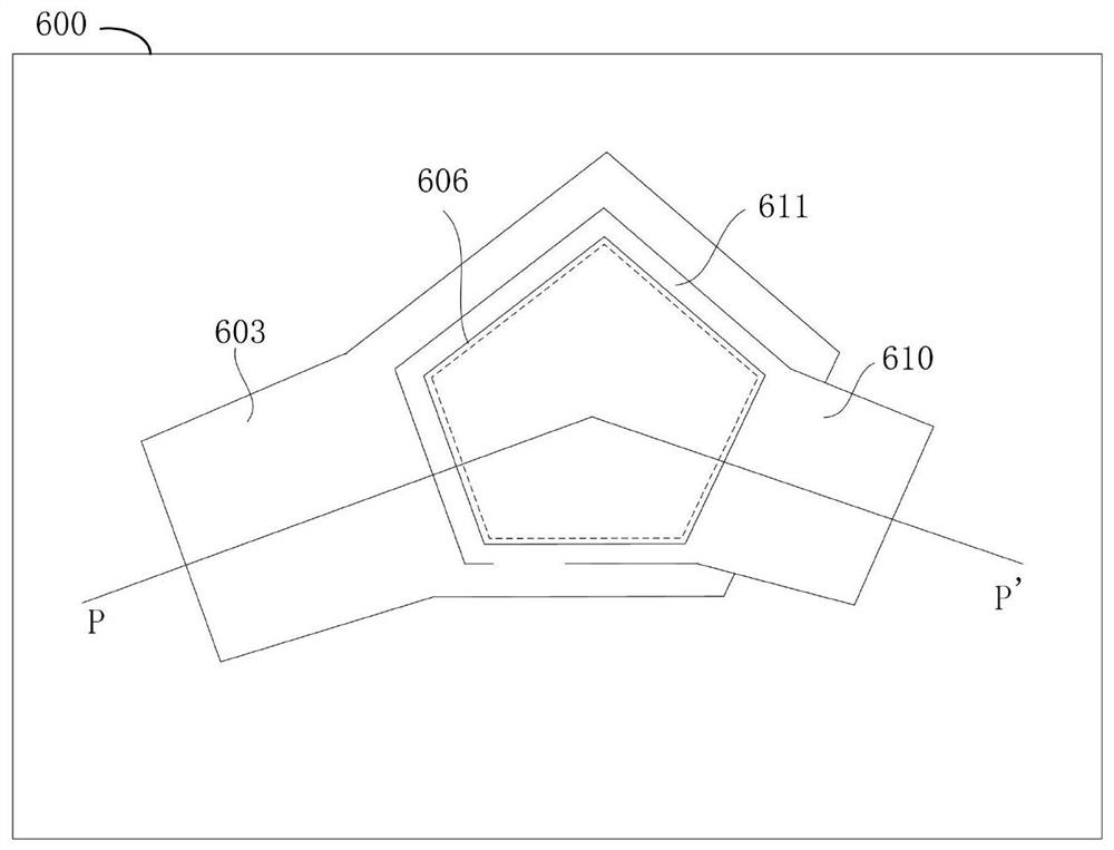
[0058] In the embodiment of the present invention, the thickness and width of the raised part provided at the connection end and the non-connection end of the top electrode of the resonator in the filter series resonator, parallel resonator and bandwidth adjustment unit are limited, further improving The insertion loss characteristics of the filter are described in detail below.

[0059] figure 2 It is a structural schematic diagram of a thin film bulk acoustic resonator provided with raised parts at both the connecting end and the non-connecting end of the top electrode. image 3 for figure 2 The cross-sectional view of the position of PP' in . Such as figure 2 and image 3 As shown, a resonator with elevated portions includes a substrate 601 , an acoustic mirror 602 , a bottom electrode 603 , a piezoelectric thin film layer (piezoelectric layer) 604 , a top electrode 605 and an elevated portion 606 . Among them, the optional material of the substrate 601 is single cr...


PUM


Abstract

The invention relates to the technical field of filters, in particular to a filter design method, a filter, a multiplexer, and a communication device. In this method, according to the design index, the thickness of the raised part of the connection end and the non-connection end of the top electrode of the resonator in the series resonator, parallel resonator, and bandwidth adjustment unit are set reasonably respectively, which can further improve the filtering The insertion loss characteristics of the device; at the same time, on the premise of achieving good insertion loss characteristics, the production cost is reduced to a certain extent, and the design flexibility is increased to a certain extent.

Description

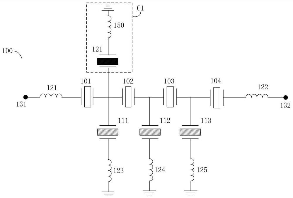
technical field [0001] The invention relates to the technical field of filters, in particular to a filter design method, a filter, a multiplexer, and a communication device. Background technique [0002] In recent years, the miniaturization and high-performance trend of communication equipment has accelerated, which poses higher challenges to the RF front-end. In the RF communication front end, on the one hand, it is necessary to achieve miniaturization by reducing the size of the chip and packaging substrate, and on the other hand, it is necessary to achieve better performance by reducing loss sources and better design methods. [0003] A typical structure of an ordinary filter is as figure 1 as shown, figure 1 It is a schematic diagram of a structure of an acoustic wave filter with a bandwidth adjusting unit according to the prior art. In this filter 100, there are inductors 121, 122 and a plurality of resonators (usually called series resonators) 101-104 between the in...

Claims


Application Information

Patent Timeline
Patent Type & Authority Patents(China)
IPC IPC(8): H03H9/02H03H9/54H03H9/70H03H9/13
CPCH03H9/02157H03H9/542H03H9/703H03H9/131H03H9/133H03H9/02086
Inventor 庞慰边子鹏
Owner ROFS MICROSYST TIANJIN CO LTD
Learn More