Connector and connector assembly

A technology of connectors and floating parts, which is applied in the direction of connection, parts of connection devices, electrical components, etc., can solve the problems of low assembly efficiency and achieve the effects of high assembly efficiency, simplified structure, and easy processing

Active Publication Date: 2020-11-17
CHINA AVIATION OPTICAL-ELECTRICAL TECH CO LTD
View PDF13 Cites 0 Cited by
  • Summary
  • Abstract
  • Description
  • Claims
  • Application Information

AI Technical Summary

Problems solved by technology

[0004] The purpose of the present invention is to provide a connector, which is used to solve the technical problem of low assembly efficiency caused by the need to assemble the signal transmission modules of the current connector one by one; in addition, the purpose of the present invention is to provide a connector components

Method used


Image

  • Connector and connector assembly
  • Connector and connector assembly
  • Connector and connector assembly

Examples


specific Embodiment 1

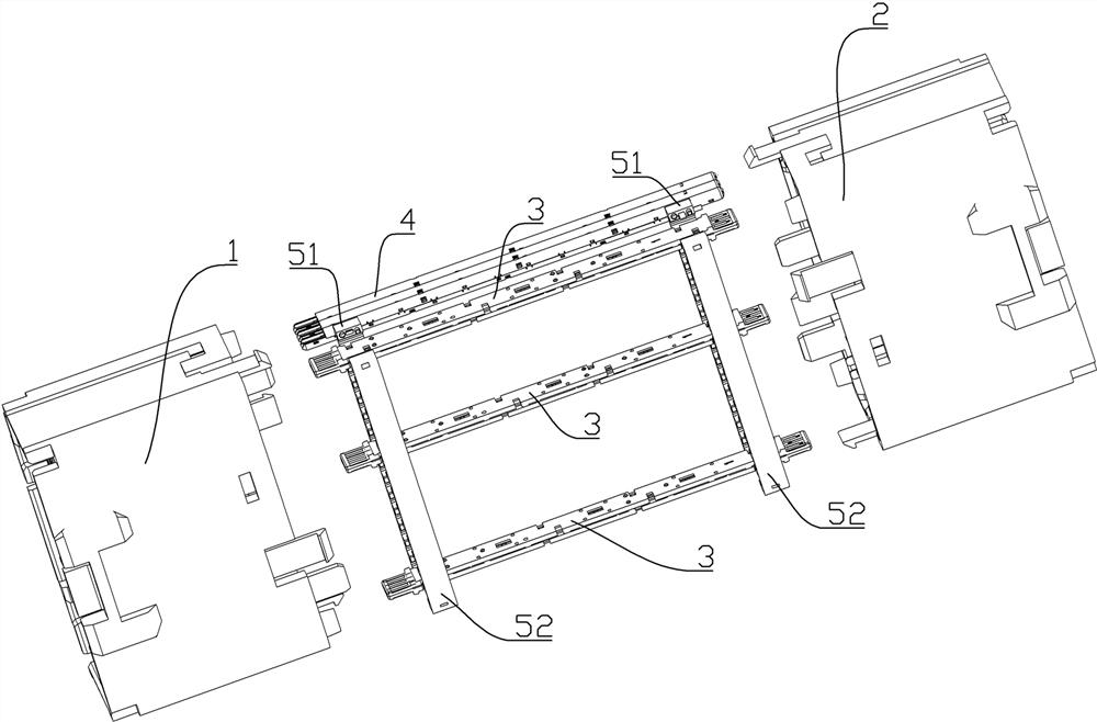
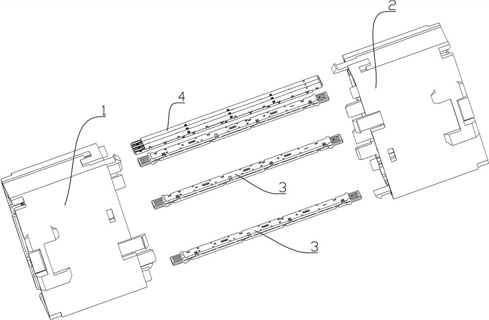
[0071] Such as figure 1 with figure 2 As shown, the connector assembly includes a transition connector, a first mating connector 1 and a second mating connector 2 adapted to the transition connector, wherein the first mating connector and the second mating connector The structure is the prior art and will not be described in detail.

[0072] The transfer connector includes a housing (not shown in the figure) and a signal transmission module arranged in the housing. The housing includes two housing units with the same structure. The opposite ends of the two housing units have a The opposite ends of the two housing units are provided with an end plate that restricts the signal transmission module from coming out, and the end plate is provided with a through hole for the signal transmission module to pass through. The shell structure is the prior art, for example, it may be the shell of the transfer connector disclosed in the application publication number CN109659755A, and th...

specific Embodiment 2

[0082] The specific embodiment 2 of the connector assembly of the present invention, the difference between the structure of the connector assembly in this embodiment and the above-mentioned specific embodiment 1 of the connector assembly is only that:

[0083] In this example, if Figure 7 As shown, the first card bar 201 and the second card bar 202 are not provided with a card slot for clearance matching with the signal transmission module, and the first card bar 201 and the second card bar 202 are all provided with L-shaped surfaces. The L-shaped surfaces on the clamping strip 201 and the second clamping strip 202 enclose the module matching hole 203 .

specific Embodiment 3

[0084] The specific embodiment 3 of the connector assembly of the present invention, the difference between the structure of the connector assembly in this embodiment and the above-mentioned specific embodiment 1 of the connector assembly is only that:

[0085] In this embodiment, the two clips are fixed by bolts. In other embodiments, when the clips are made of metal, they can also be fixed by welding; in other embodiments, the two clips can also be riveted. In other embodiments, when the clamping strips are fixed by bolts, the guide posts and guide grooves may not be provided.


PUM


Abstract

The invention relates to a connector and a connector assembly. The connector comprises a shell, signal transmission modules and module integrated floating parts, the module integrated floating parts are correspondingly matched with the at least two signal transmission modules, and the module matching holes or the module matching grooves are in clearance fit with the corresponding signal transmission modules in the direction perpendicular to the extending direction of the signal transmission modules. Floating of the signal transmission modules is not affected, meanwhile, the blocking faces on the signal transmission modules guarantee that the module integration floating pieces can move front and back and cannot disengage from the signal transmission modules, the module integration floatingpieces can integrate the corresponding signal transmission modules into a signal module set, and when the signal transmission modules are assembled into the shell, the signal module groups can be assembled concentratively. And compared with the mode of assembling the signal module groups one by one in the prior art, the assembly efficiency is improved.

Description

technical field [0001] The invention relates to a connector and a connector assembly. Background technique [0002] The existing connector assemblies between the two PCB boards are two-piece plug-in structure, the plug and the socket are plugged together, the allowable lateral offset is small, if the offset exceeds the maximum value, the plug and socket If the pressure between the conductors is too small, it is easy to cause poor conduction. [0003] The Chinese patent application with application publication number CN109659755A and application publication date of 2019.04.19 discloses a transfer connector. The transfer connector includes a housing and a signal transmission module installed in the housing. For the same housing unit, the housing unit is provided with a through hole for accommodating the signal module, and the opposite end of the housing unit is integrally formed to block and cooperate with the signal transmission module along the insertion direction of the tr...

Claims


Application Information

Patent Timeline
Patent Type & Authority Applications(China)
IPC IPC(8): H01R13/506H01R13/631
CPCH01R13/506H01R13/6315
Inventor 陈占锋马陆飞
Owner CHINA AVIATION OPTICAL-ELECTRICAL TECH CO LTD
Why Eureka
Try Eureka