
Method for determining flow rate of fluid pumped by pump

A technology for conveying volume and flow, which is applied in the detection of fluid flow by measuring differential pressure, volume/mass flow generated by mechanical effects, measurement devices, etc., which can solve problems such as increasing the complexity of the pump and occupying the installation space and reducing the efficiency of the pump.

Inactive Publication Date: 2020-11-17
LEISTRITZ PUMPEN
View PDF8 Cites 4 Cited by
  • Summary
  • Abstract
  • Description
  • Claims
  • Application Information

AI Technical Summary

Problems solved by technology

However, this increases the complexity and installation space of the pump and, depending on the type of positive displacement flowmeter used, reduces the efficiency of the pump in some cases

Method used


Image

  • Method for determining flow rate of fluid pumped by pump
  • Method for determining flow rate of fluid pumped by pump
  • Method for determining flow rate of fluid pumped by pump

Examples


Embodiment Construction

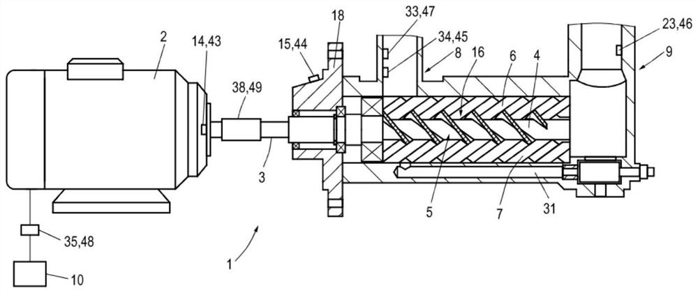
[0053] figure 1 A pump 1 is shown, in the example a progressive cavity pump. It comprises a motor 2 which drives a main screw 4 via a shaft 3 . The main screw 4 is also called drive screw. It is arranged in the vicinity of the secondary screws 6, 7 (also called running screws) so that in the resulting void 5 jointly formed by the main screw 4 and the secondary screws 6, 7, when the shaft 3 rotates, Fluid is delivered from fluid inlet 8 to fluid outlet 9 . Operating parameters of the pump 1 are recorded by a plurality of sensor devices 43 to 49 . Progressive cavity pumps are well known in the art and therefore should not be described in detail.

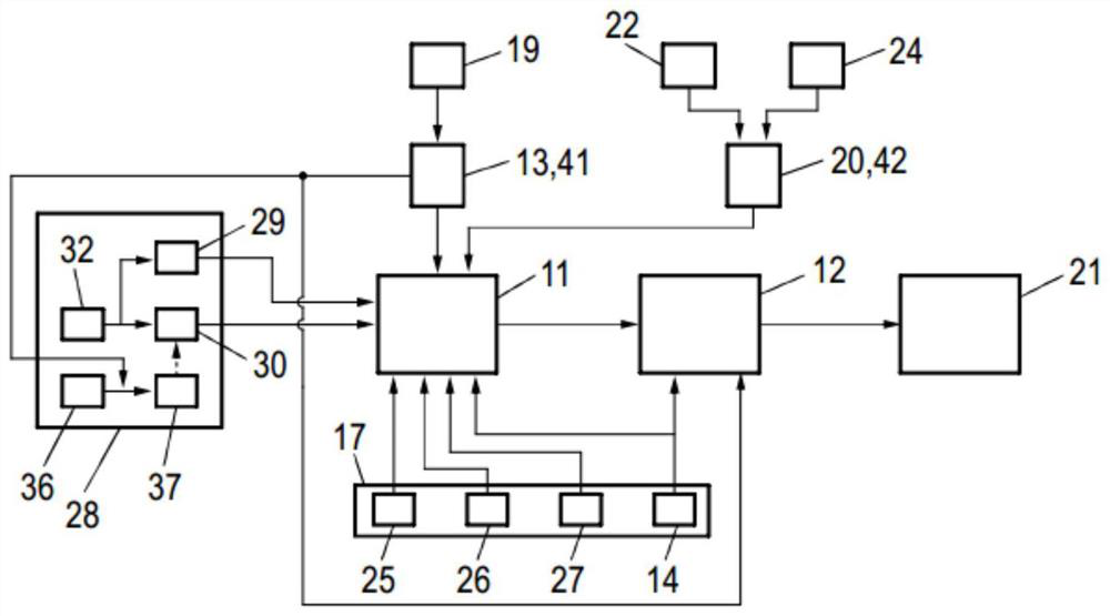
[0054] In many applications, the flow delivered from fluid inlet 8 to fluid outlet 9 is to be determined. Also refer below figure 2 options for this are listed. In principle, the leakage volume flow 11 , ie the fluid flowing back through the gap 16 in the pump 1 , can be completely ignored. In this case, the settable delivery ...


PUM


Abstract

The invention discloses a method for determining a flow rate (21) of a fluid pumped by a pump (1), wherein the flow rate (21) is determined as a function of predefined pump information (17) of a geometry of the pump, rotational speed information (41) relating to a rotational speed (13) of the pump (1), and pressure information (42) relating to a differential pressure (20) at the pump (1).

Description

technical field [0001] The invention relates to a method for measuring the flow rate of fluid delivered by a pump. Furthermore, the invention relates to a pump for conveying fluids. Background technique [0002] Pumps, especially positive displacement pumps, find use in many applications where the flow delivered by the pump is to be monitored or controlled. For this, positive displacement flow meters arranged in the feed line or discharge line of the pump can be used. However, this increases the complexity and installation space of the pump and, depending on the type of positive displacement flowmeter used, reduces the efficiency of the pump in some cases. [0003] It is therefore an object of the present invention to define an improved method for determining the flow through a pump. Contents of the invention [0004] According to the invention, this object is achieved by a method for determining the flow rate of a fluid delivered by a pump, wherein the flow rate is det...

Claims


Application Information

Patent Timeline
Patent Type & Authority Applications(China)
IPC IPC(8): G01M13/00G01F1/34G01D21/02
CPCG01M13/00G01F1/34G01D21/02F04C14/28F04C2270/20F04C2/12F04B2201/0808F04B2201/1201F04B2205/07F04C2270/21F04B2201/0803F04C2270/40F04B2205/09
Inventor 罗兰·莫里萨特奥利维尔·特罗斯曼菲利普·罗索
Owner LEISTRITZ PUMPEN
Learn More