


Quick Research
Generate reliable direction feasibility study reports for your R&D in just a few steps.

Technical Q&A
Discover and master advanced knowledge NOW. Basics, ideas, possibilities, all at once.

Find Solutions
As an expert in R&D theories, this can generate solutions to your technical problems instantly.

Evaluate Feasibility
Analyze your overall solution with one click, know your potential R&D risks in advance.

Monitor Landscape
Get weekly tech updates, stay abreast of the latest tech innovations and key insights.
Gearbox oil changing method and gearbox oil changing equipment
A technology of gearbox and equipment, applied in mechanical equipment, lubricating oil control valve, lubricating oil input and other directions, can solve the problems of abnormal transmission oil volume, strict oil temperature limit, complex structure of oil changing equipment, etc. To achieve the effect of flexible connection method and connection position, reduce procurement costs, and shorten assembly and disassembly man-hours
- Summary
- Abstract
- Description
- Claims
- Application Information
AI Technical Summary
Problems solved by technology
Method used
Image


Examples
Embodiment 1
[0058] This part will describe the specific embodiment of the present invention in detail, and the preferred embodiment of the present invention is shown in the accompanying drawings. Each technical feature and overall technical solution of the invention, but it should not be understood as a limitation on the protection scope of the present invention.
[0059] In the description of the present invention, it should be understood that the orientation descriptions, such as up, down, front, back, left, right, etc. indicated orientations or positional relationships are based on the orientations or positional relationships shown in the drawings, and are only In order to facilitate the description of the present invention and simplify the description, it does not indicate or imply that the device or element referred to must have a specific orientation, be constructed and operated in a specific orientation, and thus should not be construed as limiting the present invention.
[0060] I...
Embodiment 2
[0105] Such as Figure 4 to Figure 6 Shown, gearbox oil change equipment, including:
[0106] The second joint 18, the second joint 18 can be connected with the gearbox;
[0107] The second oil return line, the third pump body 21 and the sixth valve body 22 are arranged on the second oil return line, the third pump body 21 can realize forward rotation and reverse rotation, the sixth valve body 22 is a reversing valve, the sixth The number of liquid passages in the valve body 22 is greater than or equal to two, and the third pump body 21 can drive the liquid to be drawn out from the gearbox through the second joint 18;
[0108] The second oil injection pipeline, the third pump body 21 and the sixth valve body 22 are arranged on the second oil injection pipeline, the third pump body 21 can drive the liquid to inject into the gearbox through the second joint 18, and the sixth valve body 22 can The third pump body 21 is switched between the second oil return pipeline and the sec...
Embodiment 3
[0127] Such as Figure 7 to Figure 9 Shown, gearbox oil change equipment, including:
[0128] The third joint 28, the third joint 28 can be connected with the gearbox;
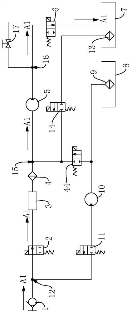
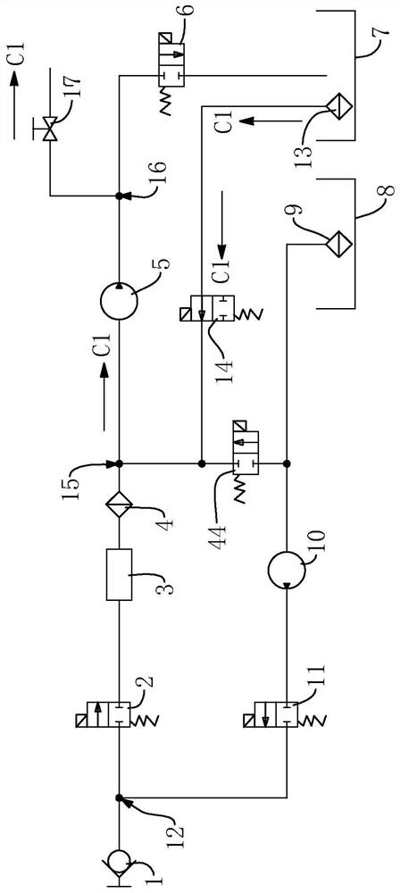
[0129] The third oil return line, the third oil return line is provided with a fourth pump body 34, an eighth valve body 32 and a ninth valve body 36, and the fourth pump body 34 is arranged between the eighth valve body 32 and the ninth valve body 36 During the interval, the fourth pump body 34 can draw liquid from the gearbox and make the liquid pass through the third joint 28, the eighth valve body 32 and the ninth valve body 36;
[0130] The third oil injection pipeline, the tenth valve body 40 and the eleventh valve body 41 are arranged on the third oil injection pipeline, the fourth pump body 34 is arranged between the tenth valve body 40 and the eleventh valve body 41, the fourth The pump body 34 can drive the liquid to flow through the tenth valve body 40 and the eleventh valve body 41 and flow into ...
PUM
 Abstract
Description
Claims
Application Information
 - R&D Engineer
- R&D Manager
- IP Professional
- Industry Leading Data Capabilities
- Powerful AI technology
- Patent DNA Extraction
Browse by: Latest US Patents, China's latest patents, Technical Efficacy Thesaurus, Application Domain, Technology Topic, Popular Technical Reports.
© 2024 PatSnap. All rights reserved.Legal|Privacy policy|Modern Slavery Act Transparency Statement|Sitemap|About US| Contact US: help@patsnap.com