Engine cylinder cover lifting appliance and locking method
What is Al technical title?
Al technical title is built by PatSnap Al team. It summarizes the technical point description of the patent document.
A technology of engine cylinder head and hoisting gear, applied in the field of hoisting gear, can solve problems such as collision accidents, damaged surfaces, easy to wear engine cylinder head, etc., and achieve safe and reliable hoisting effects
Pending Publication Date: 2020-11-17
Y & C ENGINE
View PDF0 Cites 1 Cited by
Summary
Abstract
Description
Claims
Application Information
AI Technical Summary
This helps you quickly interpret patents by identifying the three key elements:
Problems solved by technology
Method used
Benefits of technology
Problems solved by technology
[0004] First: The hooking force of the hook is easy to damage the machining accuracy of the hole or cavity on the side of the engine cylinder head;
[0005] Second: The steel wire rope or nylon rope is easy to wear the side of the engine cylinder head and damage the surface for fine milling;
[0006] Third: When driving, the engine cylinder head swings due to inertia, and it is laborious to hold the engine cylinder head by hand to restrain it from swinging. If people are too close to the engine cylinder head, it is easy to cause a collision accident
Method used
Image
Click on the blue label to locate the original text in one second.
Reading with bidirectional positioning of images and text.
Examples
Embodiment 1
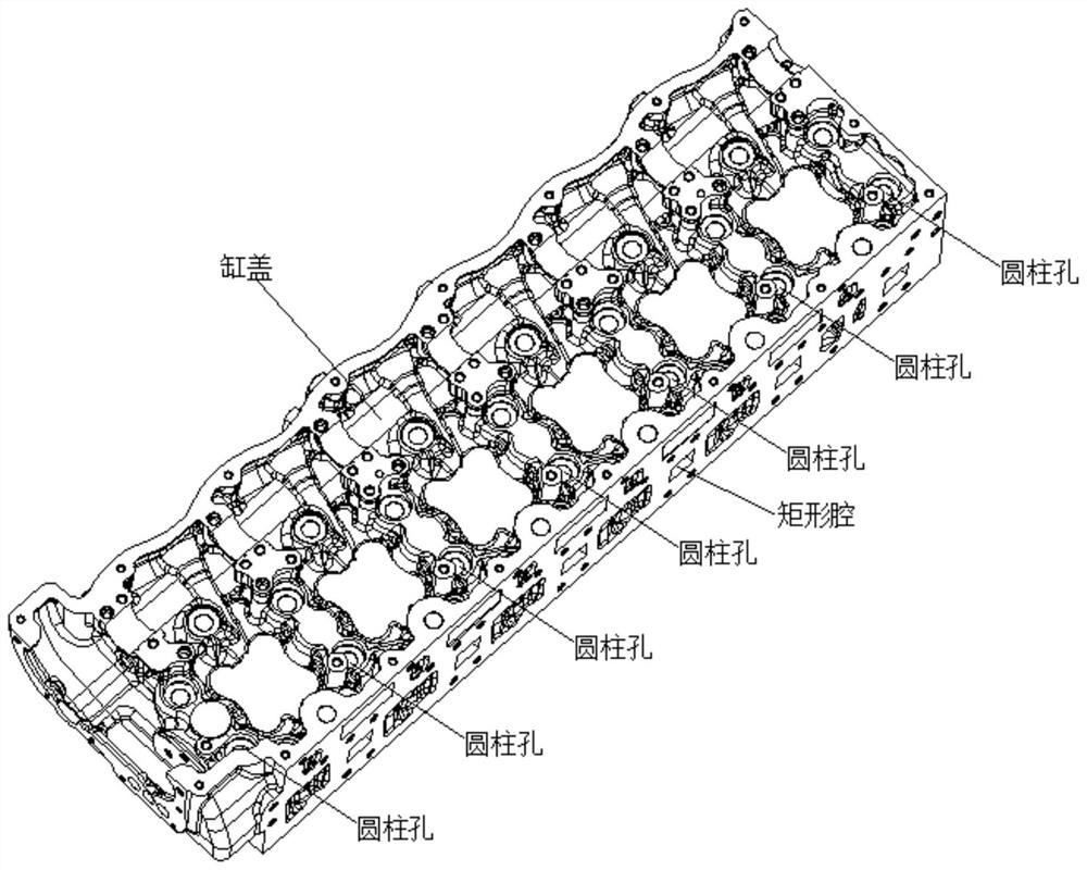
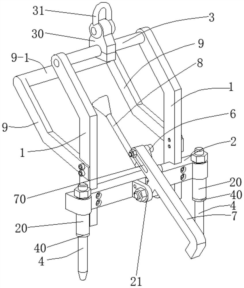
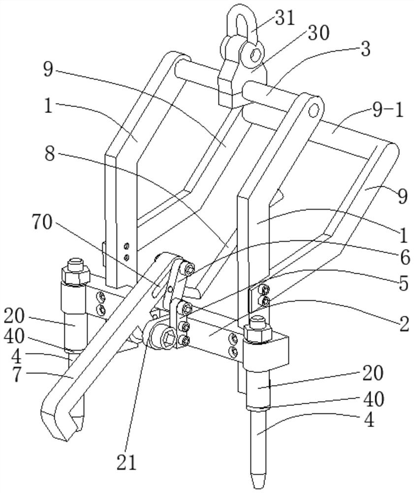
[0053] For the engine cylinder head hanger, hook the suspension ring 31 with the hook at the lower end of the vehicle, then hang the engine cylinder head hanger of the present invention to the engine cylinder head upper end, then hold the handle bar 9-1 by hand, and release the engine down. Cylinder head hanger, so that the long pin 4 is inserted into the two cylindrical holes in the middle of the upper end of the engine cylinder head, then hold the operating rod 8, straighten the operating rod 8 and push it forward, and then the connecting rod 2 6 is wound around the connecting rod The hinge of one 5 rotates forward, and the pin shaft at the upper end of the connecting rod 2 6 pushes the connecting rod 3 7 to rotate downward around the hinge seat through the long slot 70. When the connecting rod 2 6 rotates to the horizontal state, the connecting rod 3 7 Rotate to the vertical state, at this time the hook at the end of the connecting rod 3 7 is inserted into the rectangular ca...
Embodiment 2
[0058] On the basis of Embodiment 1, the lower end surface of the support cylinder 20 is flush with the lower end surface of the longitudinal arm 1, and rubber pads are attached to the lower end surface of the support cylinder 20 and the lower end of the longitudinal arm 1 to avoid the support cylinder 20 The lower end surface of the longitudinal arm 1 is directly in contact with the finishing surface of the engine cylinder head to ensure the accuracy of the finishing surface of the engine cylinder head; the longitudinal arm 1 is divided into an upper arm and a lower arm, and the angle between the upper arm and the lower arm is 110°-140°, which ensures that after the engine cylinder head is hoisted, the center of gravity of the entire engine cylinder head and the spreader is located in the middle as much as possible to ensure the horizontal hoisting of the engine cylinder head; the middle of the cross brace 3 is fastened with lifting lugs 30, the lifting lug 30 is hinged with a...
PUM
Abstract
The invention discloses an engine cylinder cover lifting appliance and a locking method. The engine cylinder cover lifting appliance comprises two longitudinal arms, a transverse arm, a transverse supporting rod, long plug pins, a connecting rod I, a connecting rod II, a connecting rod III, an operating rod and side wall rods, wherein the side walls of the lower ends of the longitudinal arms are provided with notches, the transverse arm is inserted into the notches in the longitudinal arms, two ends of the transverse supporting rod are connected with the upper ends of the longitudinal arms ina fastened mode respectively, supporting cylinders are arranged at two ends of the transverse arm, a hinge seat is arranged in the middle of the transverse arm, the long plug pins are inserted into the supporting cylinders, the upper ends of the long plug pins are locked by nuts, the connecting rod I is fixedly connected with the side wall of the hinge seat, the lower end of the connecting rod IIis hinged to the upper end of the connecting rod I, the upper end of the connecting rod II is connected with a long groove in the connecting rod III through a pin shaft, the middle part of the connecting rod III is hinged with the hinge seat, the operating rod is axially limited and circumferentially hinged with the side surface of the connecting rod II, the number of the side wall rods is two, the two side wall rods are connected with the longitudinal arms in a fastened mode, and a handle rod is arranged between the two side wall rods. The machining precision of a hole or a cavity in the sideface of an engine cylinder cover is guaranteed, the lifting is convenient and labor-saving, collision accidents are avoided, and thus the lifting is safer and more reliable.
Description
technical field [0001] The invention belongs to the technical field of hangers, in particular, the invention relates to an engine cylinder head hanger and a locking method. Background technique [0002] During the assembly process of the engine, in order to realize the closing of the valve spring by the valve spring, it is necessary to connect the upper seat of the spring to the valve through the valve lock clip. 1. Install the upper seat of the spring, and then install the camshaft. [0003] The traditional way to hoist the engine cylinder head to the workbench on the assembly line is to directly hook the hook at the lower end of the steel wire rope or nylon rope to the hole or cavity on the side of the engine cylinder head, and then hoist it by driving. [0004] First: The hooking force of the hook is easy to damage the machining accuracy of the hole or cavity on the side of the engine cylinder head; [0005] Second: The steel wire rope or nylon rope is easy to wear the ...
Claims
Application Information
Patent Timeline
Application Date:The date an application was filed.
Publication Date:The date a patent or application was officially published.
First Publication Date:The earliest publication date of a patent with the same application number.
Issue Date:Publication date of the patent grant document.
PCT Entry Date:The Entry date of PCT National Phase.
Estimated Expiry Date:The statutory expiry date of a patent right according to the Patent Law, and it is the longest term of protection that the patent right can achieve without the termination of the patent right due to other reasons(Term extension factor has been taken into account ).
Invalid Date:Actual expiry date is based on effective date or publication date of legal transaction data of invalid patent.