Pumping material valve

A valve and material technology, applied in the field of valve devices, can solve the problems of easy settling, high fluid stability, reduced valve plate sealing, etc., to achieve the effect of increasing suspension

Inactive Publication Date: 2020-11-17
铜陵爱阀科技有限公司
View PDF5 Cites 0 Cited by
  • Summary
  • Abstract
  • Description
  • Claims
  • Application Information

AI Technical Summary

Problems solved by technology

[0004] However, there are many types of liquid materials such as suspension material solutions, suspension material solutions include solvents and particles suspended in solvents, valves disclosed in the prior art, in the process of conveying pipelines, suspension materials in suspension material solutions The material is easy to settle, especially into the valve cavity with a large cavity, the settled material is easy to cause the sealing performance of the valve plate to decrease
[0005] The essential reason for the above-mentioned technical defects is that during the process of liquid flowing through the valve, the suspended material solution moves horizontally, and the fluid stability is relatively high, which causes the suspended material in the suspended material solution to enter the valve cavity, and the material settles.

Method used


Image

  • Pumping material valve
  • Pumping material valve
  • Pumping material valve

Examples


Embodiment Construction

[0044] The embodiments of the present invention are described in detail below. This embodiment is implemented on the premise of the technical solution of the present invention, and detailed implementation methods and specific operating procedures are provided, but the protection scope of the present invention is not limited to the following implementation example.

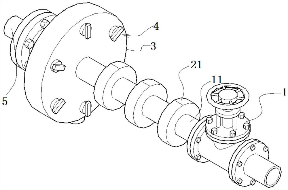
[0045] like Figure 1-9 As shown, a pump material valve includes a valve body 1, wherein the valve body 1 is a conventional valve disclosed in the prior art, and its main frame includes a valve housing, a valve plate assembled in the valve housing, and a valve for driving the valve plate. pole.

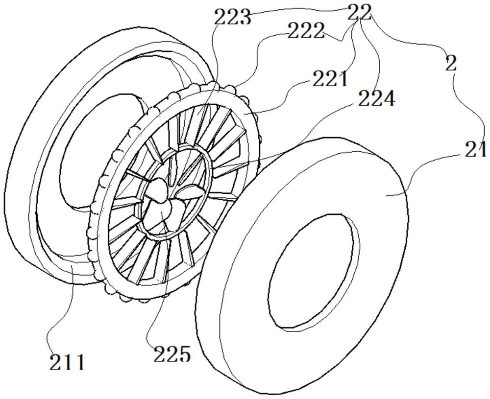
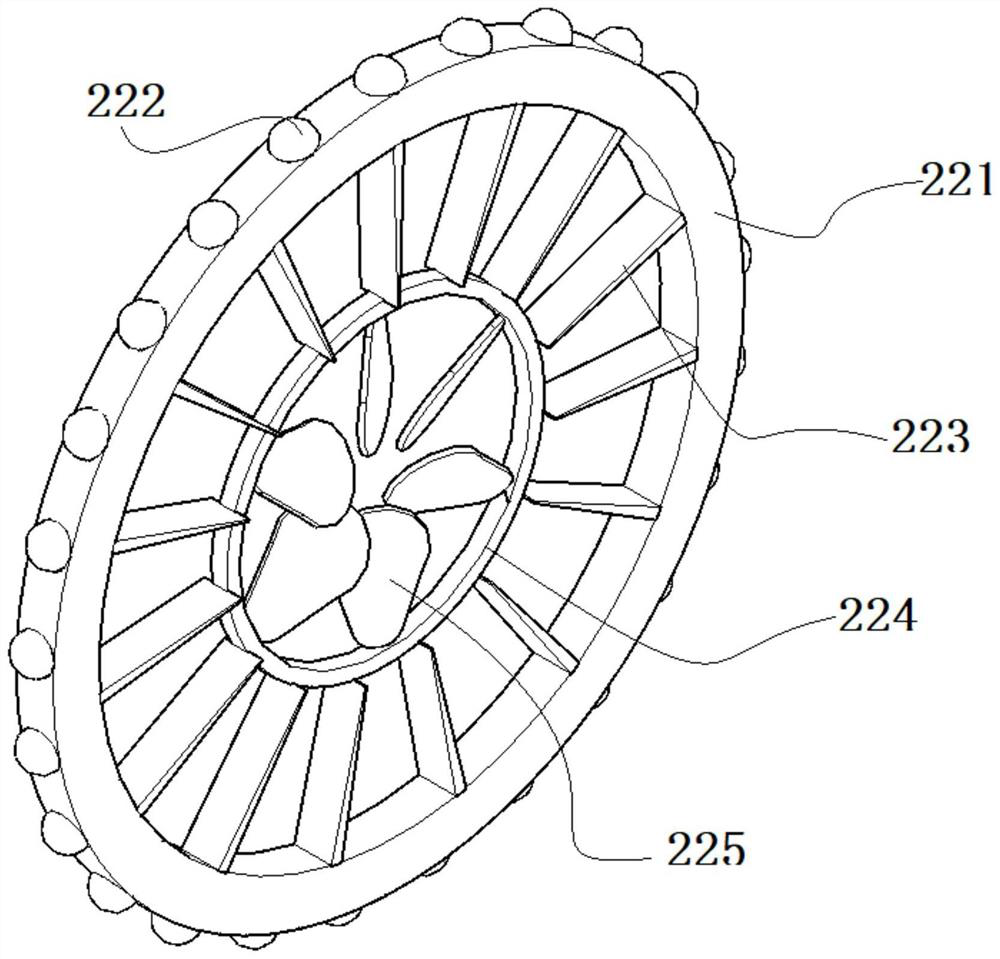
[0046] The left side of the valve body 1 is the water inlet, and the right side is the water outlet. The water inlet is connected to several stirring components 2; through the stirring components 2, the power of the material solution is used to stir the material solution and change the fluidity of the material solution. ...


PUM


Abstract

The invention discloses a material pumping valve, which comprises a valve body, and the water inlet end of the valve body communicates with a plurality of material stirring assemblies; the multiple stirring assemblies communicate with one another through communicating pipes, each stirring assembly comprises a hollow material disc, and a water-driven stirring part is rotatably connected into each material disc; the water-driven stirring part comprises a ring body rod, a plurality of rollers are limited on the outer side wall of the ring body rod, and an annular raceway matched with the rollersis formed in the inner side wall of the tray; a plurality of annularly distributed stirring plates are fixedly connected to the inner side wall of the ring body rod, a central ring rod is fixedly connected to the ends of the stirring plates, and a plurality of annularly distributed driving plates are fixedly connected to the inner side wall of the central ring rod; the driving plate is obliquely arranged; the material pumping valve further comprises a defoaming part communicated with the liquid inlet end of the material stirring assembly, wherein the material solution is defoamed through the defoaming part. By means of the design of the components of the device, the technical defect that in the material solution conveying process, the material solution settles and blocks the valve cavity is effectively overcome.

Description

technical field [0001] The invention relates to the field of valve devices, in particular to a pump material valve. Background technique [0002] A valve is a mechanical component that controls the discharge of materials. At present, valves are mainly used in the pipeline transportation process of liquid materials. [0003] However, there are many types of liquid materials, and the valves disclosed in the prior art can effectively exert the valve's function of controlling material discharge when transporting liquid materials with high uniformity. [0004] However, there are many types of liquid materials such as suspension material solutions, suspension material solutions include solvents and particles suspended in solvents, valves disclosed in the prior art, in the process of conveying pipelines, suspension materials in suspension material solutions The material is easy to settle, especially into the larger valve cavity, and the settled material will easily reduce the seal...

Claims


Application Information

Patent Timeline
Patent Type & Authority Applications(China)
IPC IPC(8): B01D19/04B01F7/00F16K51/00
CPCB01D19/04F16K51/00B01F27/13
Inventor 钱华祥王彪任晓辉陈光凯
Owner 铜陵爱阀科技有限公司
Why Eureka
Try Eureka