
Interventional valve frame and aortic valve

An interventional, frame-based technology, applied to heart valves and other directions, can solve problems such as vulnerable tissues, reduce stress concentration, enhance internal stress transfer, and reduce or alleviate adverse effects.

Pending Publication Date: 2020-11-17
SHANGHAI NEWMED MEDICAL CO LTD
View PDF0 Cites 1 Cited by
  • Summary
  • Abstract
  • Description
  • Claims
  • Application Information

AI Technical Summary

Problems solved by technology

[0004] In view of the problems in the prior art, the purpose of the present invention is to provide an interventional valve frame and aortic valve, which overcomes the problem that the two ends of the valve frame in the prior art are easily damaged when the valve frame expands, and can effectively accept the oblique rod in the middle section. The transmitted stress reduces the stress concentration of the oblique rods in the midstream section, so that the oblique rods in the midstream section are more likely to expand under force, reaching the expansion rate of the oblique rods at both ends, thus reducing or alleviating the outward expansion of the two ends when the valve frame expands to form a dog-like Adverse Effects on Bone Structure

Method used


Image

  • Interventional valve frame and aortic valve
  • Interventional valve frame and aortic valve
  • Interventional valve frame and aortic valve

Examples


Embodiment Construction

[0084] Example embodiments will now be described more fully with reference to the accompanying drawings. Example embodiments may, however, be embodied in many forms and should not be construed as limited to the embodiments set forth herein. Rather, these embodiments are provided so that this disclosure will be thorough and complete, and will fully convey the concept of the example embodiments to those skilled in the art. The same reference numerals denote the same or similar structures in the drawings, and thus their repeated descriptions will be omitted.

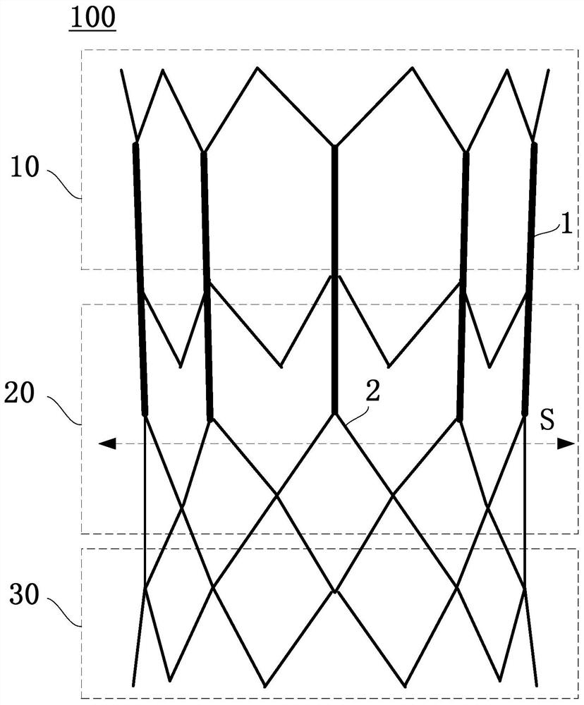
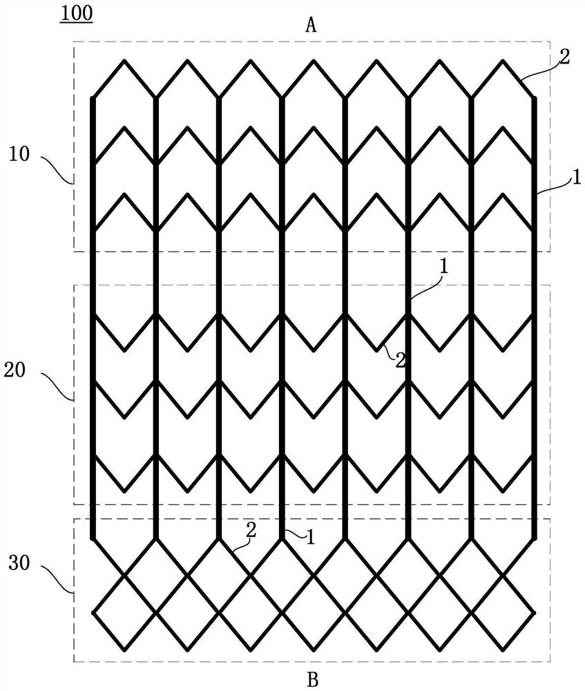
[0085] figure 2 It is a three-dimensional schematic diagram of the first interventional valve holder of the present invention. image 3 It is a flattened plan view of the first interventional valve holder of the present invention. Such as figure 2 and 3 As shown (in order to see the arrangement of the oblique rods in the interventional valve holder, image 3 The schematic diagram showing the flattened interventional...


PUM


Abstract

The invention provides an interventional valve frame and an aortic valve. The interventional valve frame comprises a valve frame body for defining a frame lumen, the valve frame body comprises straight rods connecting an upstream port and a downstream port and inclined rods connected between the straight rods, an upstream section, a midstream section and a downstream section are sequentially formed in the direction from the upstream port to the downstream port, and when the valve frame body is expanded from a compression state to an expansion state, the expansion strain provided by the inclined rods located on the midstream section to the circumferential direction of the valve frame body is larger than the expansion strain provided by the inclined rods located on the upstream section and / or the downstream section to the circumferential direction of the valve frame body, so that the rate difference between the circumferential expansion rate of the midstream section and the circumferential expansion rate of the upstream section and / or the downstream section is compensated. According to the interventional valve frame and the aortic valve, by effectively receiving the stress transmitted by the inclined rods on the midstream section, the stress concentration of the inclined rods on the midstream section is reduced, so that the inclined rods on the midstream section is prone to be stressed and expand to achieve the expansion rate of the inclined rods at the two ends, and then the adverse effect that the two ends expand outwards to form a dog-bone-like structure when the valve frame expands is reduced or relieved.

Description

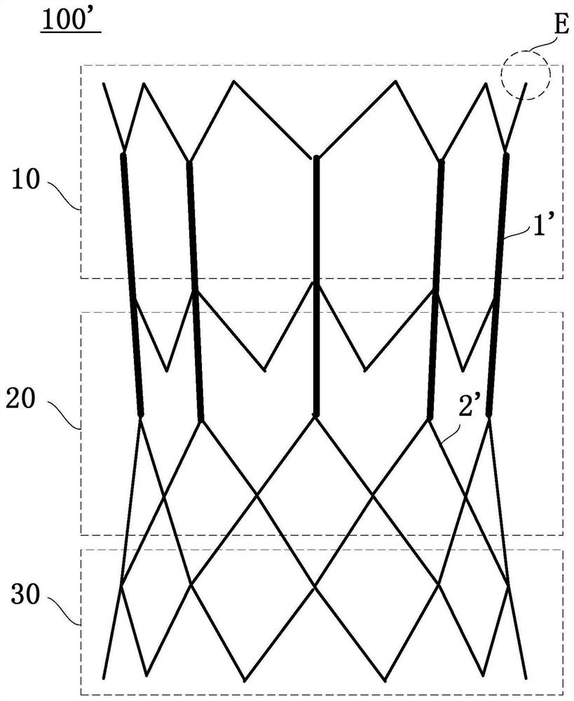
technical field [0001] The invention relates to the field of minimally invasive medical devices, in particular to an interventional valve holder and an aortic valve. Background technique [0002] figure 1 It is a three-dimensional schematic diagram of an interventional valve holder in the prior art. Such as figure 1 As shown, the existing interventional valve holder 100' is composed of a straight rod 1 and an oblique rod 2. Since the upstream section 10, the midstream section 20, and the downstream section 30 of the interventional valve holder 100' are in different positions, during the expansion process In this case, there will be a dog-bone effect, that is, when the valve frame delivery system is inflated to the maximum recommended filling pressure, the diameters of the proximal and distal ends of the frame are larger than the diameter of the middle end of the frame, and the frame looks like a dog bone at this time. This is because during the expansion process of the va...

Claims


Application Information

Patent Timeline
IPC IPC(8): A61F2/24
CPCA61F2/24A61F2/2427A61F2/2418A61F2250/0048A61F2250/0036A61F2/90A61F2230/0054A61F2250/001
Inventor 虞奇峰秦涛其他发明人请求不公开姓名
Owner SHANGHAI NEWMED MEDICAL CO LTD
Learn More