Labyrinth seal with oil scraping structure and oil scraping method
A technology of labyrinth seal and oil scraper, applied in the direction of engine sealing, engine lubrication, engine components, etc., can solve the problems of leaking grease, insufficient sealing performance, inability to adapt, etc., and achieve the effect of preventing leakage and good sealing.
- Summary
- Abstract
- Description
- Claims
- Application Information
AI Technical Summary
Problems solved by technology
Method used
Image
Examples
Embodiment 1
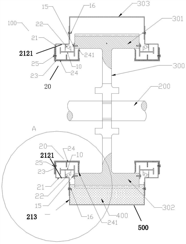
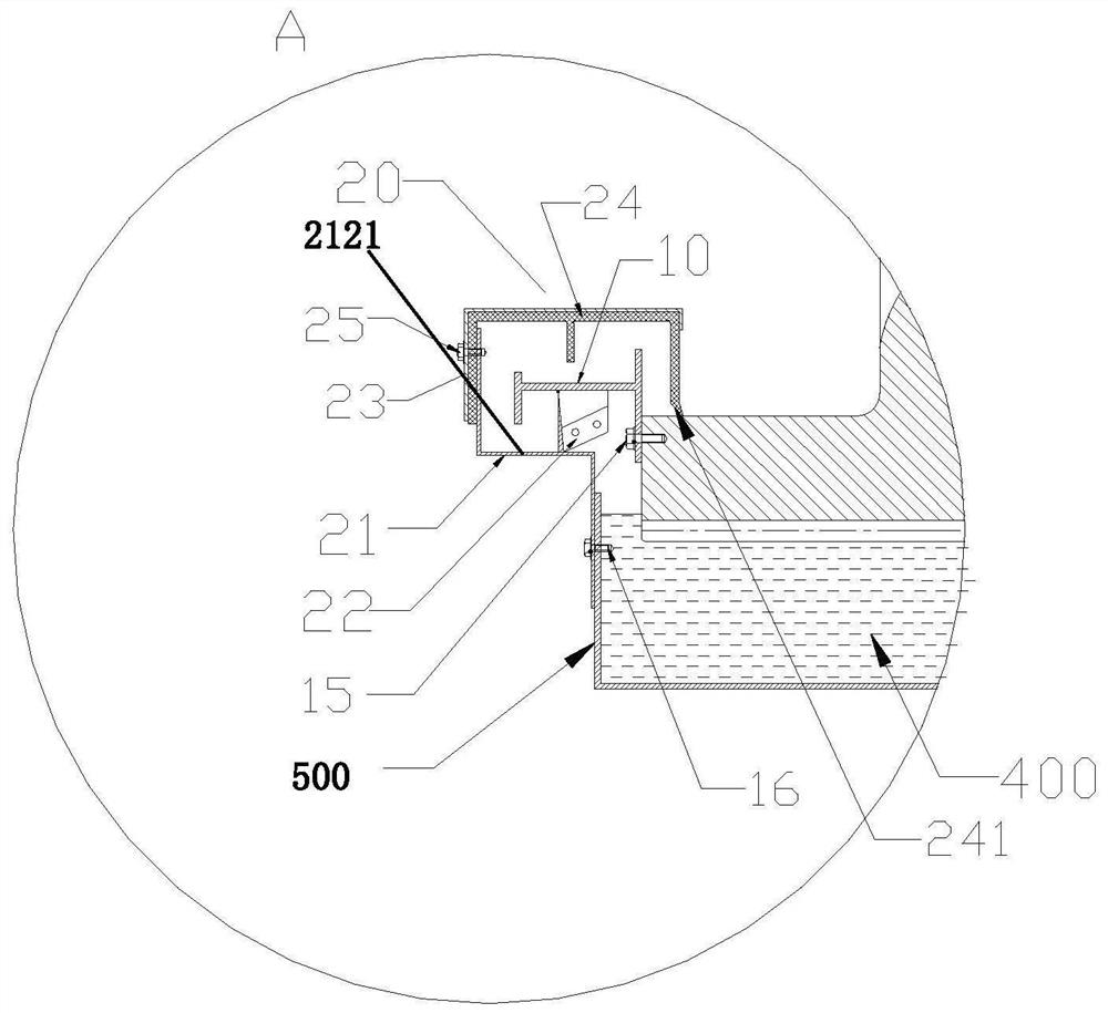
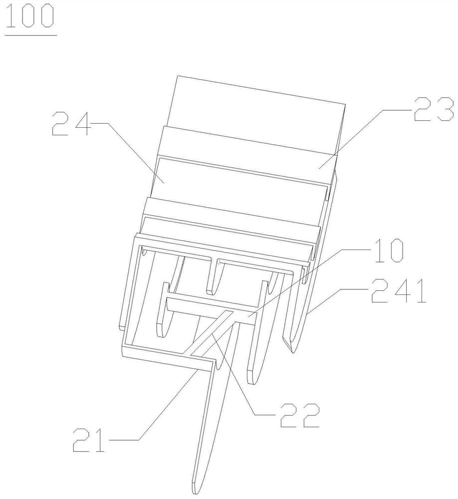
[0053] Such as Figure 1-6 As shown, the present invention provides a labyrinth seal with an oil scraping structure. The labyrinth seal 100 includes a moving ring 10 fixedly installed on the gear 300 and a static ring 20 fixedly installed on the gear cover 303. The moving ring 10 accommodates Inside the stationary ring 20, at least one oil scraper 22 is provided on one side of the stationary ring 20 against the surface of the moving ring 10, and the oil scraper 22 is used to move the gear 300 axially The lubricating grease 400 on the end face is scraped to the oil storage tank formed by the gear cover lower section 3031 of the gear cover 303 .
[0054] By setting an oil scraper 22 on the inner wall of one side of the static ring 20 against the surface of the movable ring 10, when the movable ring 10 starts to rotate with the gear 300, the oil scraper 22 can move the distance between the movable ring 10 and the static ring 20. The lubricating grease in the gap is scraped and s...
Embodiment 2
[0070] Such as Figure 7 As shown, the labyrinth seal 100 also includes at least one scraper adjuster 30, the scraper adjuster 30 includes a sleeve 31, an elastic member 36 and a locking member, and the sleeve 31 is fixedly installed on the static In the installation hole of the ring 20, the elastic member 36 is installed in the cavity of the sleeve 31, and one end of the elastic member 36 is against one side of the oil scraper 22, so that the oil scraper 22 The other side is against the surface of the moving ring 10 , and the other end of the elastic member 36 is provided with a locking member fixed in the cavity of the sleeve 31 . Wherein the oil scraper 22 can be made of flexible material. The elastic member 36 can be designed as a compression spring.
[0071] In order to ensure the tight and flexible fit between the side of the oil scraper 22 and the surface of the moving ring 10, an elastic member 36 is provided on one side of the oil scraper 22, that is, the oil scrape...
Embodiment 3
[0075] Such as Figure 8 As shown, the number of the oil scraper 22 is four, and each of the oil scraper 22 is evenly distributed on the inner peripheral surface of the stationary ring 20 .
[0076] By distributing each oil scraper plate 22 evenly on the inner peripheral surface of the stationary ring 20, it is ensured that the upper and lower sections of grease in the gap between the moving ring 10 and the stationary ring 20 are scraped to the oil storage tank below. .
[0077] preferred, such as Figure 5 , 6 , 8, the first end 221 of each oil scraper 22 is set to be close to the axial end face of the gear 300, and the second end of each oil scraper 22 is set to be away from the axial end of the gear 300 The end face, each of the oil scraper 22 and the axial end face of the gear 300 has a certain inclination angle, and the inner surface of each of the oil scraper 22 faces the axis of the stationary ring 20 so that the lubricating oil returns to the gear In the oil storag...
PUM
 Abstract
Description
Claims
Application Information
 - R&D
- Intellectual Property
- Life Sciences
- Materials
- Tech Scout
- Unparalleled Data Quality
- Higher Quality Content
- 60% Fewer Hallucinations
Browse by: Latest US Patents, China's latest patents, Technical Efficacy Thesaurus, Application Domain, Technology Topic, Popular Technical Reports.
© 2025 PatSnap. All rights reserved.Legal|Privacy policy|Modern Slavery Act Transparency Statement|Sitemap|About US| Contact US: help@patsnap.com


