
A kind of drilling equipment for wooden stool board installation

A wooden bench technology for installation, which is applied to wood processing appliances, manufacturing tools, fixed drilling machines, etc., and can solve problems such as cumbersome movements

Active Publication Date: 2022-07-08
临沂临港国有资产运营集团有限公司
View PDF10 Cites 0 Cited by
  • Summary
  • Abstract
  • Description
  • Claims
  • Application Information

AI Technical Summary

Problems solved by technology

[0005] In order to overcome the above disadvantages that the wooden stool board needs to be taken out and placed manually after the hole is opened, and the action is cumbersome, and the wood chips need to be manually cleaned after the wooden stool board is taken out after the hole is opened, the technical problem to be solved is to provide an automatic push-out Hole opening equipment for wooden bench boards with complete holes and automatic cleaning of sawdust for wooden bench boards with holes completed

Method used


Image

  • A kind of drilling equipment for wooden stool board installation
  • A kind of drilling equipment for wooden stool board installation
  • A kind of drilling equipment for wooden stool board installation

Examples


Embodiment 1

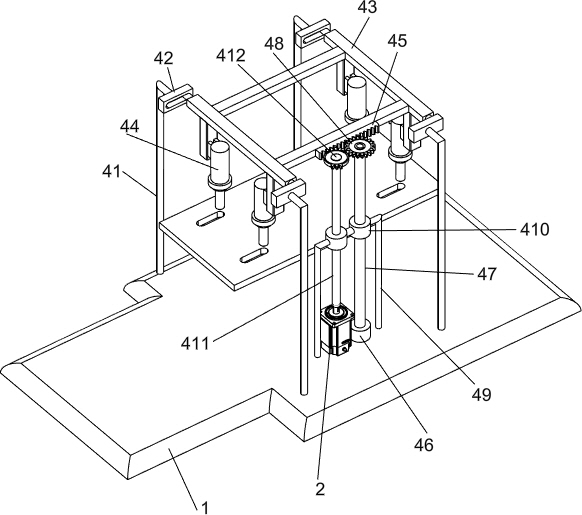
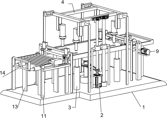
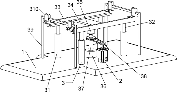
[0023] A kind of drilling equipment for wooden stool board installation, such as Figure 1-6 As shown, it includes a base 1, a servo motor 2, a lifting mechanism 3 and an opening mechanism 4. A servo motor 2 is arranged in the middle of the front side of the top of the base 1, and a lifting mechanism 3 is arranged in the middle of the top of the base 1. The lifting mechanism 3 is located in the servo motor 2 On the rear side, a hole-opening mechanism 4 is provided in the middle of the top of the base 1 , and the hole-opening mechanism 4 is located directly above the lifting mechanism 3 .

[0024] The lifting mechanism 3 includes a first sliding sleeve 31, a sliding rod 32, a first support frame 33, a connecting plate 34, a threaded sleeve 35, a first bearing seat 36, a threaded rod 37, a belt transmission assembly 38, a fixed rod 39 and a fixed block 310, first sliding sleeves 31 are symmetrically arranged on both front and rear sides of the top of the base 1, the first slidin...

Embodiment 2

[0030] On the basis of Example 1, as figure 1 and Figure 4-6 As shown, it also includes a mounting plate 5, a third rotating shaft 6, a rubber roller 7, a second full gear 8, a deceleration motor 9 and a second supporting frame 10. The right side of the top of the base 1 is symmetrically provided with a mounting plate 5 front and rear, on both sides The mounting plate 5 is located on the right side of the first support frame 33 , a third rotating shaft 6 is arranged symmetrically up and down between the two mounting plates 5 , the third rotating shaft 6 on both sides is located between the upper parts of the two mounting plates 5 , and the third rotating shaft on both sides is 6 are provided with rubber rollers 7, the rear ends of the third rotating shafts 6 on both sides are provided with second full gears 8, the two second full gears 8 are meshed with each other, and the upper part of the front side of the front mounting plate 5 is provided with a reduction motor 9, which r...


PUM


Abstract

The invention relates to a hole opening device, in particular to a hole opening device for installing a wooden stool board. The technical problem to be solved is to provide a hole-opening device for installing a wooden bench board, which can automatically push out the wooden bench board with holes and automatically clean the wood chips of the wooden bench boards with holes. A hole-opening device for installing a wooden stool board, comprising: a base, the base is used to support the whole device; a servo motor, the servo motor is arranged in the middle of the top of the base; a lifting mechanism, the lifting mechanism is arranged at the In the middle of the top of the base, the lifting mechanism is located on the rear side of the servo motor, and the lifting mechanism is connected with the output shaft of the servo motor. The invention achieves the effect of automatically pushing out the wooden bench board with holes and automatically cleaning the wood chips for the wooden bench boards with holes. The wooden stool board after the hole is opened is moved out to the left, so as to realize the purpose of automatically pushing out the wooden stool board after the hole is opened.

Description

technical field [0001] The invention relates to a hole opening device, in particular to a hole opening device for installing a wooden stool board. Background technique [0002] Wooden bench is also called "bench". It is a seat with a wooden surface and no backrest. Most of them are narrow and long. The wooden bench is composed of wooden bench legs and wooden bench boards. The wooden bench legs are similar to the pillars in the building. , similar to a roof in a building. [0003] The wooden stool board is generally made of thick solid wood. After the wooden stool board is processed, four mounting holes for installing the wooden stool legs need to be opened at the four corners of the wooden stool board. Place it at the opening position. After fixing, turn on the drilling machine for drilling. After opening the hole, you need to manually remove it and then place a new wooden bench board for drilling. Manual removal is less safe and cumbersome. After the hole is taken out, th...

Claims


Application Information

Patent Timeline
Patent Type & Authority Patents(China)
IPC IPC(8): B27C3/04B27M3/18
CPCB27C3/04B27M3/18
Inventor 熊林勇
Owner 临沂临港国有资产运营集团有限公司
Learn More