
Compact type double-tooth anti-backlash mechanical single pendulum head

A compact, single-swing head technology, used in metal processing mechanical parts, large fixed members, milling machine equipment, etc., can solve the problems of large torque and small enough volume, eliminate backlash, reduce overall dimensions, and reduce overall compact effect

Pending Publication Date: 2020-11-13
KEDE NUMERICAL CONTROL CO LTD
View PDF0 Cites 4 Cited by
  • Summary
  • Abstract
  • Description
  • Claims
  • Application Information

AI Technical Summary

Problems solved by technology

[0003] In response to the above problems, the present invention researches and designs a compact double-tooth anti-backlash mechanical single pendulum head to solve the shortcomings of the traditional single pendulum milling head that is difficult to achieve a sufficiently small volume and a sufficiently large torque at the same time

Method used


Image

  • Compact type double-tooth anti-backlash mechanical single pendulum head
  • Compact type double-tooth anti-backlash mechanical single pendulum head
  • Compact type double-tooth anti-backlash mechanical single pendulum head

Examples


Embodiment 1

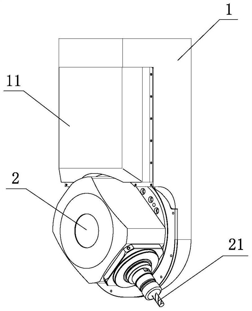
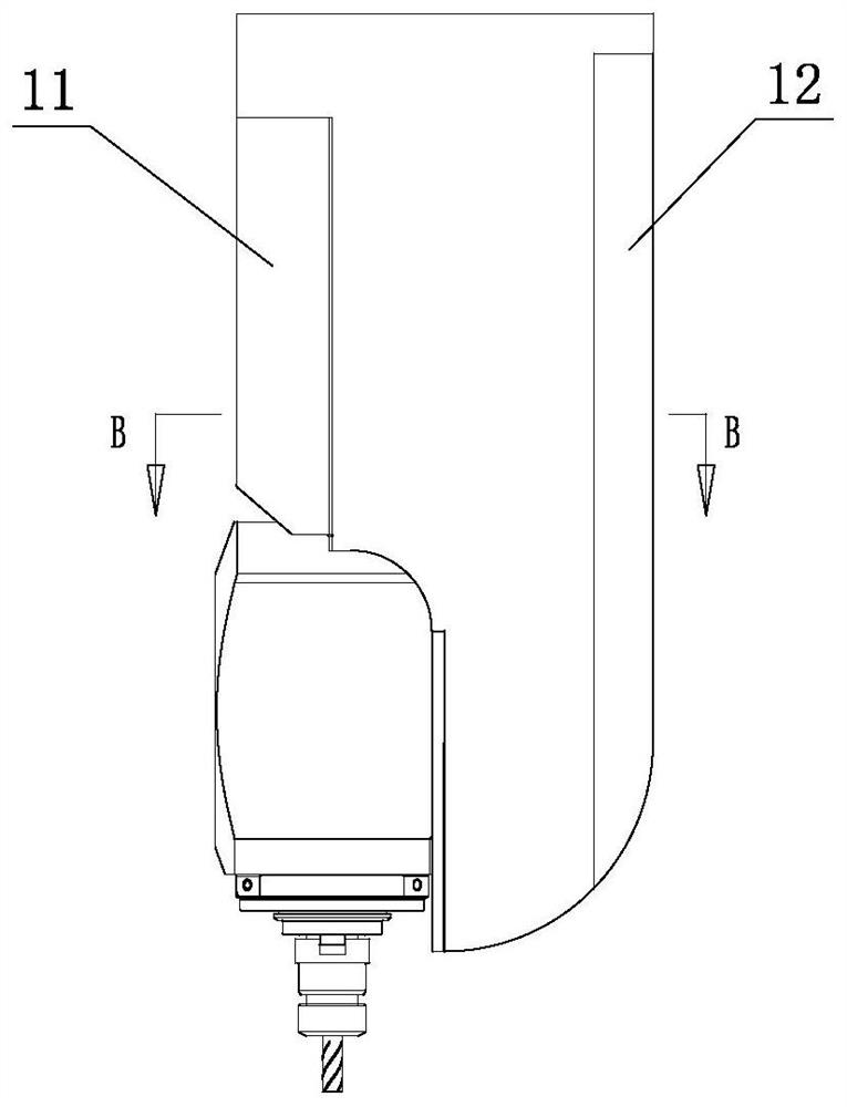
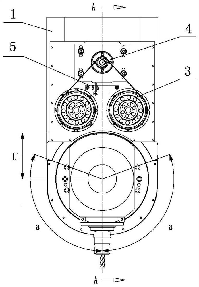
[0037] Such as Figure 1-14 As shown, a compact dual-tooth anti-backlash mechanical single swing head includes a box body 1, a main shaft 2, a transmission mechanism 3 and a driving device 4. Drive device 4 selects motor 41 for use, specifically can select servo motor for use, can make control speed and position accuracy very accurate, is provided with motor mounting hole 14 on the casing 1, and the rear end (output end of motor) of motor mounting hole 14 is provided with motor The mounting plate 42 is used for mounting and positioning the motor 41 . The transmission mechanism 3 and the driving motor are all located in the casing 1, and the casing 1 is provided with a front protective case 11 and a rear protective case 12, and each component in the casing 1 is protected by the front protective case 11 and the rear protective case 12. Transmission mechanism 3 comprises driving pulley 31, synchronous belt 32, driven pulley 33, speed reducer 34, driving gear 35 and driven gear 3...

Embodiment 2

[0049] Such as Figure 15-16 As shown, the difference from Embodiment 1 is that the rollers 51 on the first connecting rod 52 and the second connecting rod 53 are all arranged on the inside of the synchronous belt 32, the spring 54 is always in a compressed state, and the two ends of the spring 54 produce The elastic force makes the first connecting rod 52 and the second connecting rod 53 open along the pivot 55, and the rollers 51 on the first connecting rod 52 and the second connecting rod 53 will support the synchronous belt 32, so that the synchronous belt 32 is in the Tension state, to ensure normal transmission. If the synchronous belt 32 slacks after working for a period of time, the position of the spring 54 can be manually adjusted regularly (the adjustment principle is the same as in embodiment 1), that is, the two ends of the spring 54 are connected with the distance adjustment hole 56 farther away from the pivot 55 to Increase the tension of the synchronous belt 3...


PUM


Abstract

The invention discloses a compact type double-tooth anti-backlash mechanical single pendulum head. The double-tooth anti-backlash mechanical single pendulum head comprises a box body, a main shaft, atransmission mechanism and a driving device, wherein the transmission mechanism and the driving device are arranged in the box body, the transmission mechanism comprises a driving pulley, a synchronous belt, a driven pulley, a speed reducer, a driving gear and a driven gear, and the driving pulley is connected with the output end of the driving device; the driving pulley and the driven pulley areconnected through the synchronous belt, the driven pulley is connected with the input end of the speed reducer, the output end of the speed reducer is connected with the driving gear, the driving gearis meshed with the driven gear, the driven gear is connected with the main shaft, and the driven gear can drive the main shaft to rotate. The transmission mechanism disclosed by the invention can carry out three-stage speed reduction to realize a large reduction ratio and output large torque; and meanwhile, due to the fact that the output torque is large, the torque needed by a single pendulum head can be met by using a small motor, the overall dimension of the motor is reasonably reduced, the internal structure of the pendulum head is compact, and the volume space occupied by the whole pendulum head can be reduced.

Description

technical field [0001] The invention relates to an oscillating angle milling head of a numerically controlled machine tool, in particular to a compact double-tooth backlash-eliminating mechanical single-oscillating head. Background technique [0002] CNC machine tools play an important role in various fields such as industrial production and manufacturing, and milling cutters and milling heads are the main processing devices. For a single pendulum milling head, its volume and processing method largely determine the applicable processing range of the milling head. Small volume is more conducive to processing complex curved surfaces. wider. However, the reduction in volume of the single pendulum milling head means that the volume of the drive motor must also be reduced, resulting in insufficient torque required by the milling head and affecting the production efficiency of the process. If a torque motor is used for driving, stable torque can be output, but no matter whether ...

Claims


Application Information

Patent Timeline
IPC IPC(8): B23Q1/25B23Q5/56B23C9/00
CPCB23C9/005B23Q1/25B23Q5/56
Inventor 邓鑫陈虎杜长林李亚鹏张海波孙宏伟韦志鸿郭翠娟张国帅陈连君张国靖
Owner KEDE NUMERICAL CONTROL CO LTD
Learn More