
An optical system wavefront measurement device and method

An optical system and wavefront measurement technology, applied in the field of optical detection, can solve problems such as low detection accuracy and environmental disturbance, and achieve the effects of accurate defocus, high real-time performance, and strong vibration resistance

Active Publication Date: 2021-10-12
XI'AN INST OF OPTICS & FINE MECHANICS - CHINESE ACAD OF SCI
View PDF2 Cites 0 Cited by
  • Summary
  • Abstract
  • Description
  • Claims
  • Application Information

AI Technical Summary

Problems solved by technology

[0007] In order to solve the technical problems that the existing optical system wavefront measurement scheme is easily affected by environmental disturbances and has low detection accuracy, the present invention provides an optical system wavefront measurement device and method

Method used


Image

  • An optical system wavefront measurement device and method
  • An optical system wavefront measurement device and method
  • An optical system wavefront measurement device and method

Examples


Embodiment Construction

[0060] The present invention will be described in detail below in conjunction with the accompanying drawings.

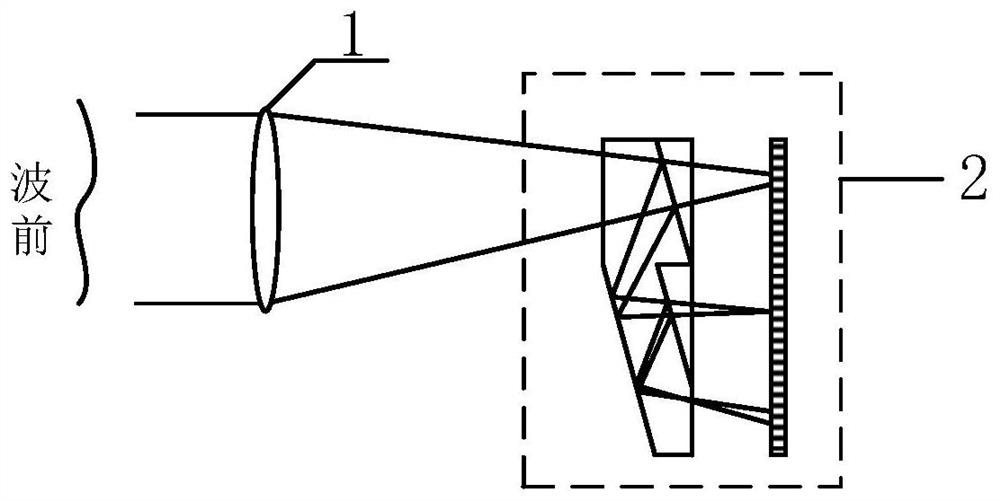
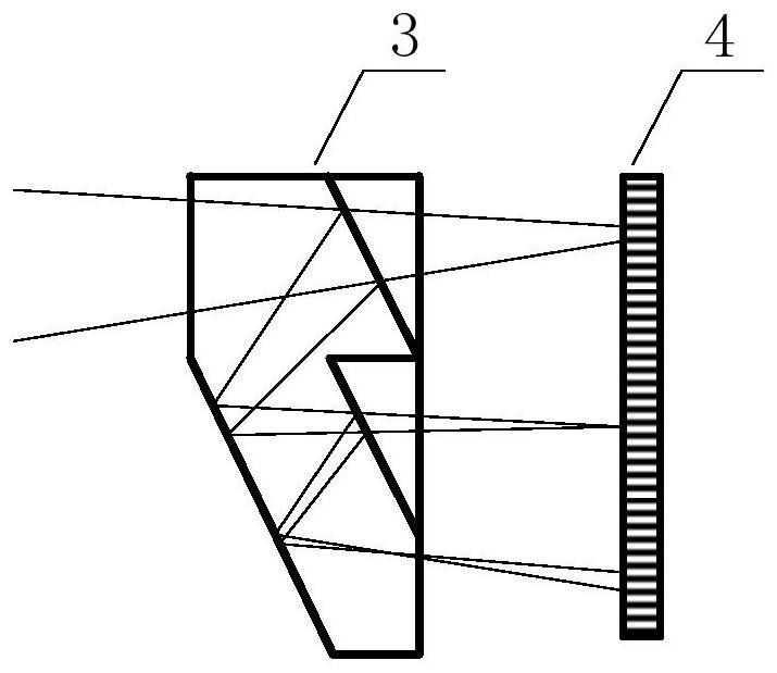
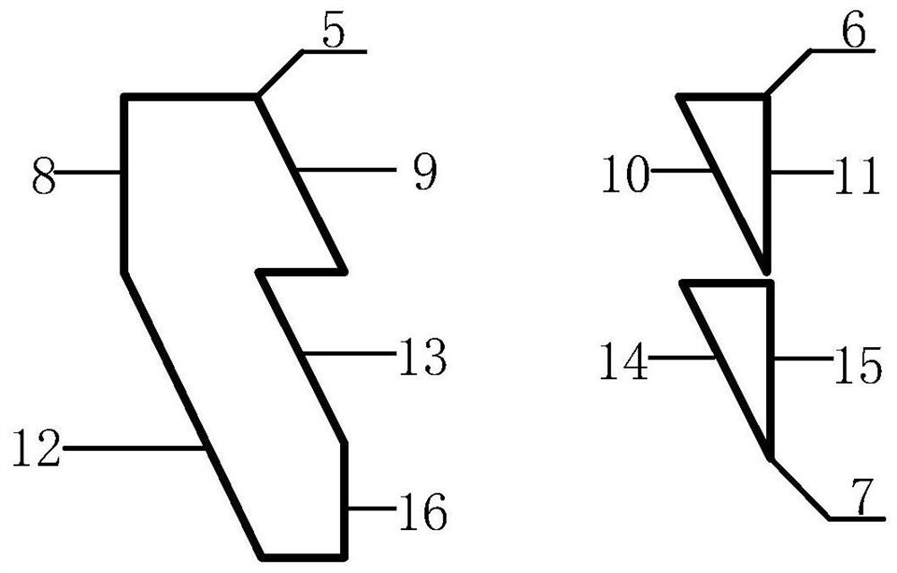
[0061] Such as figure 1 , 2 As shown, the wavefront measurement device 2 provided by the present invention is composed of a spliced ​​beamsplitter prism 3 and a detector 4 . The spliced ​​dichroic prism 3 is formed by gluing the first dichroic prism 5, the second dichroic prism 6 and the third dichroic prism 7, and the material of the prisms can be general glass material.

[0062] The first dichroic prism 5 comprises the first prism surface 8, the second prism surface 9, the third prism surface 13, the fourth prism surface 16 and the fifth prism surface 12; the first prism surface 8, the second prism surface 9, the third prism surface 13. The surface 16 of the fourth prism is coated with an antireflection film, and the surface 12 of the fifth prism is coated with a high reflection film.

[0063] The second dichroic prism 6 includes a sixth prism surface 10 and a s...


PUM


Abstract

In order to solve the technical problems that existing optical system wavefront measurement solutions are easily affected by environmental disturbances and have low detection accuracy, the present invention provides an optical system wavefront measurement device and method. The present invention first designs a spliced ​​beam splitting prism to split the light beam near the focal plane of the optical system, and installs a detector behind the beam splitting prism to form a wavefront detection device; The focal plane image, the in-focus image and the after-focus image; after the image is acquired, the wavefront of the system is obtained using an iterative method based on angular spectrum propagation. The invention has strong anti-vibration ability, little influence by air flow disturbance, simple structure, low cost, high dynamic range and measurement precision.

Description

technical field [0001] The invention belongs to the field of optical detection, and relates to an optical system wavefront measurement device and method. Background technique [0002] The resolution of the optical system can be improved by reducing the detection wavelength and increasing the aperture of the optical system, and the detection wavelength is usually determined by the optical system of the research target of the astronomical observation system. This makes it possible to obtain high resolution only by increasing the aperture of the optical system. Therefore, the aperture of the telescope is also getting larger and larger. It is difficult to process and install a single large-aperture primary mirror, and for space optical systems, they are difficult to launch, so the existing technology tends to manufacture splicing systems and multi-aperture systems as the next generation of telescopes. [0003] The goal of the splicing system and the multi-aperture system is th...

Claims


Application Information

Patent Timeline
Patent Type & Authority Patents(China)
IPC IPC(8): G01J9/00G01M11/02
CPCG01J9/00G01J2009/002G01M11/0257
Inventor 鄂可伟赵建科周艳李坤王涛李晶薛勋赵怀学刘尚阔
Owner XI'AN INST OF OPTICS & FINE MECHANICS - CHINESE ACAD OF SCI
Learn More