Medical postoperative leg massage device
A medical and leg technology, which is applied to the field of post-operative leg massage devices for medical use, can solve the problems of not being able to massage while applying medicine, poor calf comfort, etc., and achieve the effect of increasing the massage comfort.
- Summary
- Abstract
- Description
- Claims
- Application Information
AI Technical Summary
Problems solved by technology
Method used
Image
Examples
Embodiment 1
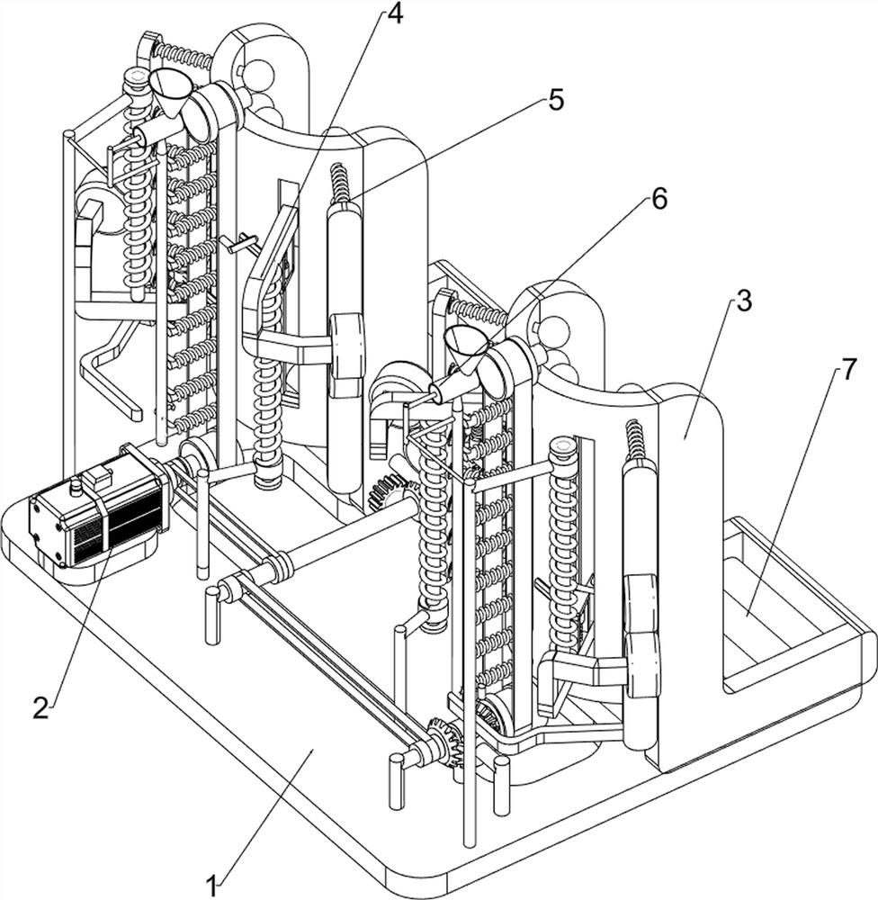
[0062] A postoperative leg massage device for medical use, such as figure 1 As shown, it includes a base plate 1, a motor 2, a foot frame 3, a rolling massage mechanism 4 and an intermittent hammering mechanism 5. The motor 2 is connected to the front left side of the base plate 1, and the foot frame 3 is connected to the left and right sides of the rear portion of the base plate 1. A rolling massage mechanism 4 is connected between the foot frame 3 and the base plate 1, the rolling massage mechanism 4 is connected with the output shaft of the motor 2, and an intermittent hammering mechanism 5 is connected between the rolling massage mechanism 4 and the foot frame 3.
[0063] When people need to massage their legs, they first step on the foot frame 3, the calf fits the parts of the intermittent hammering mechanism 5, and then start the motor 2, and the output shaft of the motor 2 rotates clockwise to drive the rolling massage mechanism 4 to rotate , so that people's shanks are m...
Embodiment 2
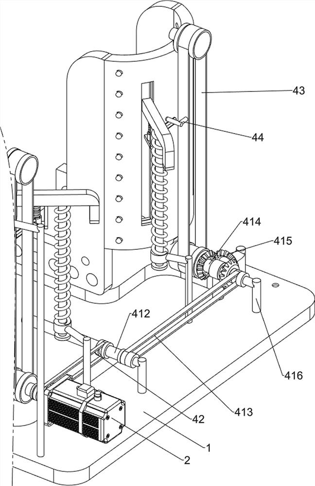
[0065] On the basis of Example 1, such as Figure 2-4 As shown, the rolling massage mechanism 4 includes a first rotating shaft 41, a first transmission assembly 42, a second transmission assembly 43, a first fixed rod 403, a driving rod 44, a first sliding sleeve 45, a first connecting rod 46, a first Spring 47, connecting frame 48, rotating rod 49, torsion spring 409, rotating rod 410, massage wheel 411, second rotating shaft 412, third transmission assembly 413, third rotating shaft 414, first bevel gear 415 and second fixed rod 416 , the output shaft of the motor 2 is connected with a first rotating shaft 41, the top of the foot frame 3 is connected with a first fixed rod 403 in a rotating manner, and the left side of the bottom plate 1 is connected with a second rotating shaft 412 in a rotating manner, and the second rotating shaft 412 is located in the motor 2 On the right side, the first transmission assembly 42 is connected between the second rotating shaft 412 and the...
Embodiment 3
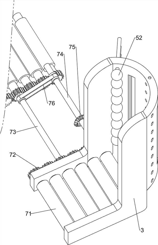
[0070] On the basis of Example 2, such as Figure 5-8 As shown, an intermittent application mechanism 6 is also included, and the intermittent application mechanism 6 includes a water pipe 61, a sponge ball 62, a third spring 63, a medicine storage tank 64, a third fixed rod 65 and a piston 66, and the middle part of the foot frame 3 evenly slides A sponge ball 62 is connected in the same way, and a downpipe 61 is connected between the front sides of the sponge ball 62 on the same side, and a medicine storage tank 64 is connected to the top of the downpipe 61, and a third fixing rod 65 is connected to the first sliding sleeve 45 on the outside. , the rear side of the third fixed rod 65 is in contact with the lower water pipe 61, the top of the third fixed rod 65 is connected with a piston 66, the piston 66 is slidingly connected with the medicine storage tank 64, and the rear side of the lower water pipe 61 is evenly connected with the foot frame 3 The third spring 63 is both ...
PUM
 Abstract
Description
Claims
Application Information
 - R&D Engineer
- R&D Manager
- IP Professional
- Industry Leading Data Capabilities
- Powerful AI technology
- Patent DNA Extraction
Browse by: Latest US Patents, China's latest patents, Technical Efficacy Thesaurus, Application Domain, Technology Topic, Popular Technical Reports.
© 2024 PatSnap. All rights reserved.Legal|Privacy policy|Modern Slavery Act Transparency Statement|Sitemap|About US| Contact US: help@patsnap.com


