Temperature difference assembly part, assembly method and light rigid body assembly with temperature difference assembly part

A temperature difference and component technology, applied in the field of temperature difference assembly components, can solve problems such as short circuits, changes in metal properties, risks, etc., and achieve the effects of rapid assembly and disassembly, greatly reduced material preparation costs, and increased flexibility

Pending Publication Date: 2020-11-06
MINTRON ENERGY TECH CO LTD
View PDF0 Cites 0 Cited by
  • Summary
  • Abstract
  • Description
  • Claims
  • Application Information

AI Technical Summary

Problems solved by technology

[0004] Furthermore, when two dissimilar metals are connected to each other, often due to the difference in oxidation-reduction potential of the two, an oxidation half-reaction on one side and a reduction half-reaction on the other side are caused, resulting in the different properties of the two metals. In addition, the long-term tight fit of two dissimilar metals will also lead to partial mutual solubility, resulting in changes in the properties of the metals
On the other hand, the clamping and bonding of two metal materials with each other will also cause some unnecessary short-circuit effects. For example, when the battery core of an electric vehicle is short-circuited, if the battery core is supported by a metal bracket, the short-circuit will be caused. The discharge of the discharge is quickly conducted to other parts, causing unnecessary risks

Method used


Image

  • Temperature difference assembly part, assembly method and light rigid body assembly with temperature difference assembly part
  • Temperature difference assembly part, assembly method and light rigid body assembly with temperature difference assembly part
  • Temperature difference assembly part, assembly method and light rigid body assembly with temperature difference assembly part

Examples


Embodiment Construction

[0031] The present invention will be further elaborated below in conjunction with the accompanying drawings and specific embodiments. These examples should be understood as only for illustrating the present invention but not for limiting the protection scope of the present invention. After reading the contents of the present invention, those skilled in the art can make various changes or modifications to the present invention, and these equivalent changes and modifications also fall within the scope defined by the claims of the present invention.

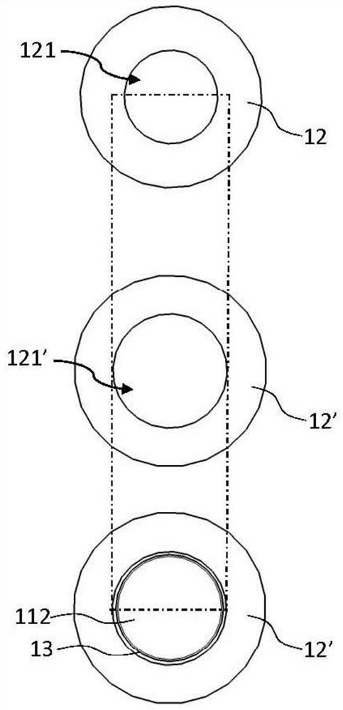
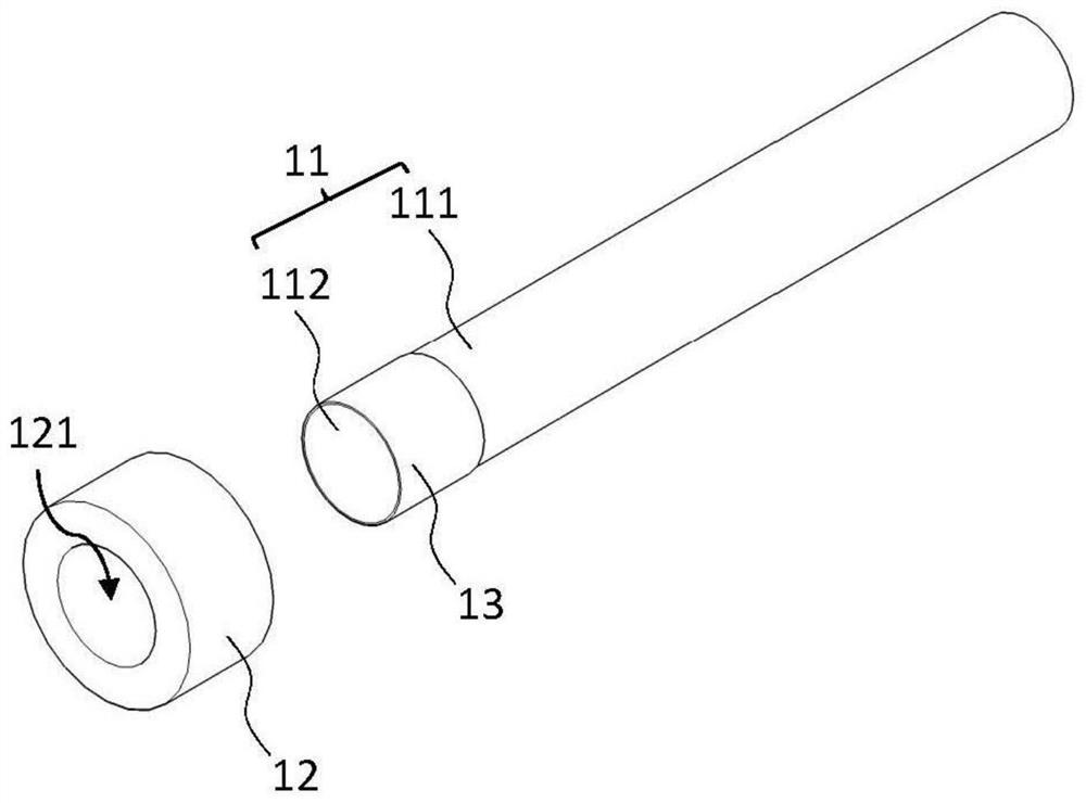
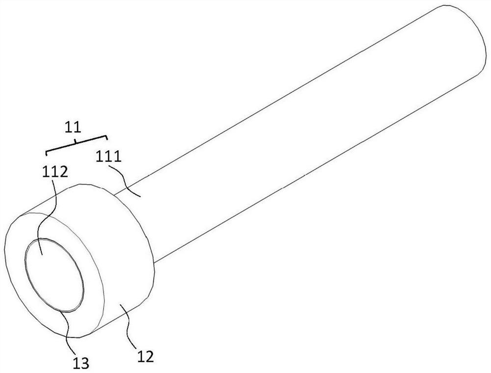
[0032] Figure 1 to Figure 3 It is a schematic diagram and a perspective view of the first preferred embodiment of the temperature difference assembly member of the present invention, the subject 11 is in the shape of a long straight cylinder, has a subject 111 and a subject 112 extending from the subject 111, and the surface of the subject 112 is formed with low heat Transfer layer 13, low heat transfer layer 13 belongs to high th...


PUM


Abstract

The invention discloses a temperature difference assembly part, which comprises a controlled part, a temperature difference assembly part, a temperature difference assembly part and a temperature difference assembly part, clamping part, at least one clamping space corresponding to the shape of the controlled part is formed in the clamping part; the clamping space has a size slightly smaller than that of the controlled part; when the temperature of the clamping part is higher than the temperature of the to-be-processed part and reaches a preset temperature difference value, the clamping space can just allow the to-be-processed part to get in and out, and when the temperature difference between the clamping part and the to-be-processed part is smaller than the preset temperature difference value, the size of the clamping space tightly clamps the to-be-processed part of the to-be-processed part; and the low heat transfer layer is arranged between the controlled part and the position, where the clamping space is formed, of the clamping part, and the low heat transfer layer has a heat conduction value lower than that of the controlled part and that of the clamping part. In addition, theinvention further discloses an assembling method of the temperature difference assembling part and a light rigid body assembly with the temperature difference assembling part.

Description

technical field [0001] The invention relates to a temperature-difference assembly component. In addition, the invention also relates to an assembly method of the temperature-difference assembly component and a light-weight rigid body assembly with the component. Background technique [0002] Generally, traditional metal structures are combined by means of welding, bonding or threading, but the structural strength of these joints is usually weak; When a collision occurs, the weld is the most likely place to break; when the structure of the above-mentioned combination is to be disassembled, in addition to the complicated disassembly process, usually there will be traces of welding or bonding after disassembly; on the other hand, if the joint is threaded, it may There will be problems of sliding teeth, screw hole cracking, screw hole precision or looseness. Moreover, the cost of the mold and stamping equipment of the above joint structure is even higher, and the manufacturing ...

Claims


Application Information

Patent Timeline
IPC IPC(8): G06F30/10B23P11/02
CPCB23P11/02B23P11/025
Inventor 庄嘉明黄振声
Owner MINTRON ENERGY TECH CO LTD
Why Eureka
Try Eureka