
Corrosion-resistant high-strength composite resin U-shaped drainage ditch

A composite resin and drainage ditch technology, which is applied to drainage structures, water supply devices, waterway systems, etc., can solve the problems of corroding drainage ditch, shortening the service life of drainage ditch, clogging of drainage ditch, etc., so as to prolong the service life and improve the anti-corrosion effect , Guarantee the effect of normal use

Inactive Publication Date: 2020-11-06
安徽绿洲危险废物综合利用有限公司
View PDF8 Cites 2 Cited by
  • Summary
  • Abstract
  • Description
  • Claims
  • Application Information

AI Technical Summary

Problems solved by technology

[0003] The existing patent (notification number: CN 210066962 U) discloses a sealed connection resin concrete U-shaped drainage ditch, which includes a U-shaped body, a drainage groove arranged in the body, and a drainage groove fixed on the outside of the first end of the body. The U-shaped first reinforcing rib on the wall, the U-shaped second reinforcing rib fixed on the outer wall of the second end of the body, and at least one third reinforcing rib fixed in the middle of the outer wall of the body, the inventor It is found that there are at least the following problems in the prior art that have not been resolved: 1. The sealed connection resin concrete U-shaped drainage ditch is easy to accumulate a large amount of sundries inside the drainage ditch during long-term use, thereby causing the blockage of the drainage ditch and affecting the quality of the drainage ditch. Normal use; 2. The seal is connected to the resin concrete U-shaped drain, and some corrosive residues remain on the drain, which corrodes the drain and shortens the service life of the drain

Method used


Image

  • Corrosion-resistant high-strength composite resin U-shaped drainage ditch
  • Corrosion-resistant high-strength composite resin U-shaped drainage ditch
  • Corrosion-resistant high-strength composite resin U-shaped drainage ditch

Examples


Embodiment Construction

[0024] In order to make the technical means, creative features, goals and effects achieved by the present invention easy to understand, the present invention will be further described below in conjunction with specific embodiments.

[0025] In the description of the present invention, it should be noted that the terms "upper", "lower", "inner", "outer", "front end", "rear end", "both ends", "one end", "another end" The orientation or positional relationship indicated by etc. is based on the orientation or positional relationship shown in the drawings, and is only for the convenience of describing the present invention and simplifying the description, rather than indicating or implying that the referred device or element must have a specific orientation, use a specific Azimuth configuration and operation, therefore, should not be construed as limiting the invention. In addition, the terms "first" and "second" are used for descriptive purposes only, and should not be understood ...


PUM


Abstract

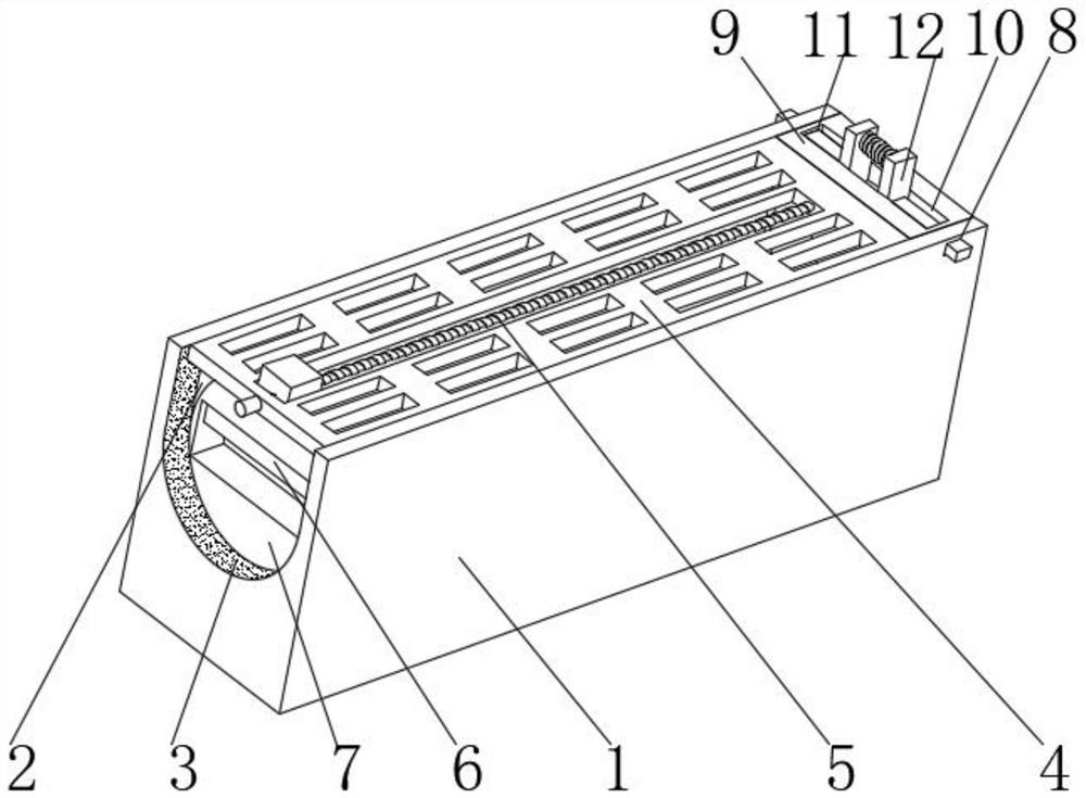
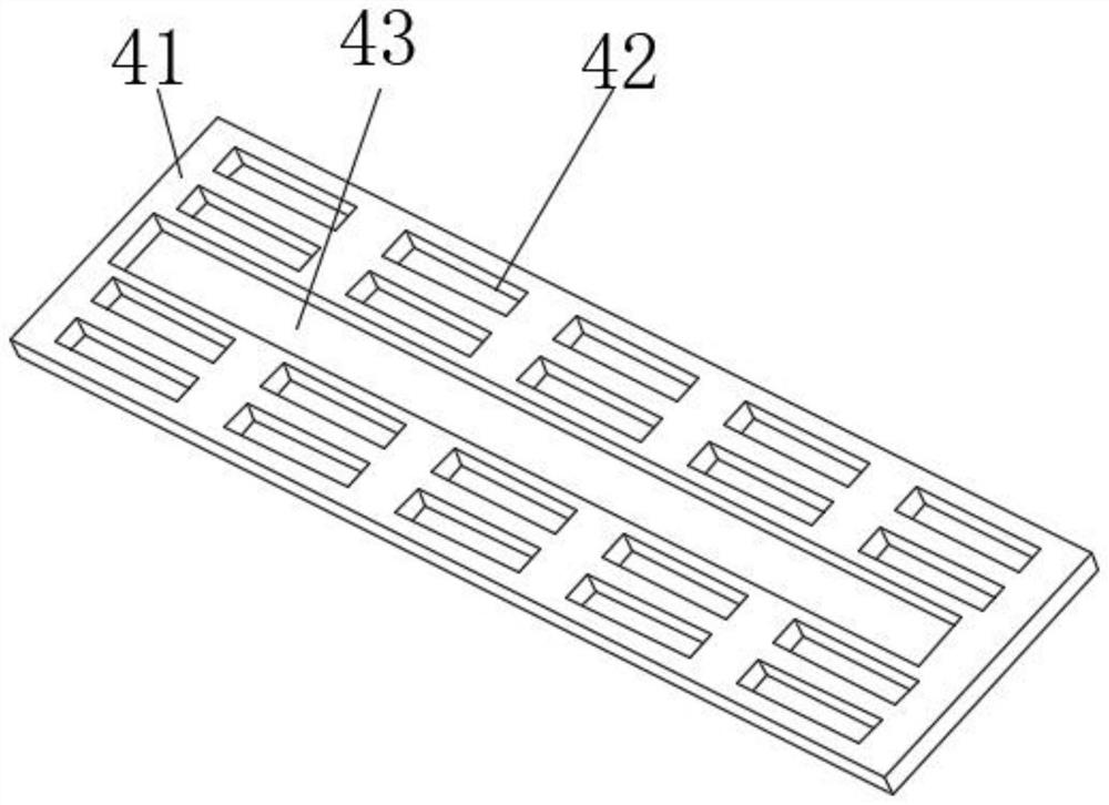
The invention discloses a corrosion-resistant high-strength composite resin U-shaped drainage ditch. The corrosion-resistant high-strength composite resin U-shaped drainage ditch comprises a drainageditch body, a U-shaped groove is formed in the upper end of the drainage ditch body, a zinc coating is fixedly installed on the groove wall of the U-shaped groove, a perforated strainer device is arranged on the upper portion of the groove wall of the U-shaped groove, a sliding device is arranged in the middle of the perforated strainer device, a stretchable isolation device is arranged on the left portion of the lower end of the sliding device, a cleaning device is arranged on the left portion of the groove wall of the U-shaped groove, through grooves are formed in the upper side of the rightportion of the front end of the drainage ditch body and the upper side of the right portion of the rear end of the drainage ditch body correspondingly, a supporting plate is movably connected to theupper side of the right portion of the groove wall of the U-shaped groove, and a filtering and storing device is arranged on the groove wall of a concentric-square-shaped groove. According to the corrosion-resistant high-strength composite resin U-shaped drainage ditch, first movable plates on the two sides are manually pressed, so that a storage box is conveniently taken out of the U-shaped groove, sundries are cleared away, the sundries are prevented from being accumulated in the drainage ditch body to cause blockage, and normal use of the drainage ditch body is guaranteed.

Description

technical field [0001] The invention relates to the field of drainage ditch equipment, in particular to a corrosion-resistant high-strength composite resin U-shaped drainage ditch. Background technique [0002] The drainage ditch refers to the ditch that guides the water collected in the side ditch, the intercepting ditch, and the low-lying places near the roadbed, in the crop field, and near the residence to the ditch outside the roadbed, crop field, and residential area. The design of the drainage ditch is based on the layout and engineering standards of the drainage system. Determine the depth and spacing of drainage ditches in the field, and analyze and calculate the flow, water level, section size and engineering quantity of drainage ditches and buildings at all levels. Drainage ditches are generally arranged at both ends or lower ends of intercepting ditches on slopes for Exclude surface runoff that cannot be accommodated by the intercepting ditch, and the terminal of ...

Claims


Application Information

Patent Timeline
Patent Type & Authority Applications(China)
IPC IPC(8): E03F5/04E03F5/06B01D29/01
CPCB01D29/01E03F5/04E03F5/041E03F5/06
Inventor 谢付元袁胜巧付二龙
Owner 安徽绿洲危险废物综合利用有限公司
Learn More