
A kind of bearing defect detection equipment

A defect detection and bearing technology, applied in the direction of mechanical bearing testing, measuring devices, testing of mechanical parts, etc., to achieve the effect of improving detection accuracy and detection value

Active Publication Date: 2022-07-29
温岭市微米自动化设备有限公司
View PDF16 Cites 0 Cited by
  • Summary
  • Abstract
  • Description
  • Claims
  • Application Information

AI Technical Summary

Problems solved by technology

[0004] The related technologies mentioned above can detect the rotational resistance of the bearing when it rotates. At present, there is no detection equipment that can detect whether the bearing has cracks or debris defects.

Method used


Image

  • A kind of bearing defect detection equipment
  • A kind of bearing defect detection equipment
  • A kind of bearing defect detection equipment

Examples


Embodiment 1

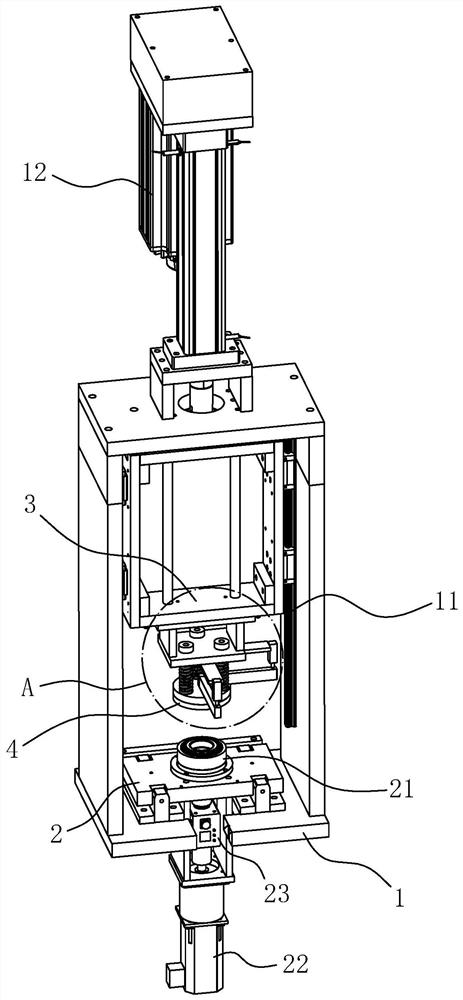
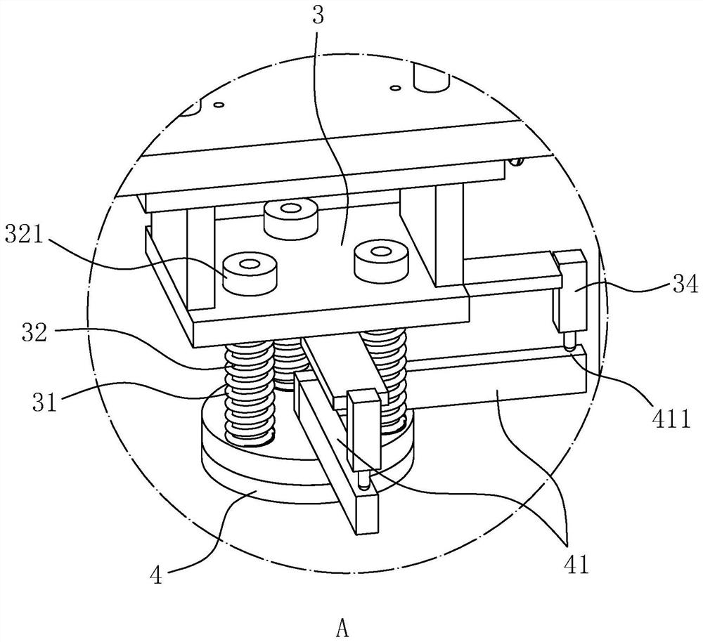
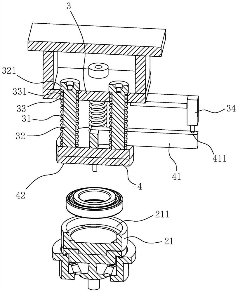
[0036] The embodiment of the present application discloses a bearing defect detection device. refer to figure 1 , the bearing defect detection equipment includes a frame 1, the frame 1 is provided with a mounting frame 2, the mounting frame 2 is provided with a mounting seat 21, a drive motor 22 that drives the mounting seat 21 to rotate, and the mounting seat 21 is used to place the to-be-detected bearing. The rack 1 is also slidably provided with a top seat 3, the top seat 3 is located directly above the mounting frame 2, and the bottom surface of the top seat 3 is provided with a pressure head 4, and the pressure head 4 and the mounting seat 21 are respectively used for the two bearings of the bearing to be detected. A ring is fixed.

[0037] The sliding direction of the top seat 3 is in the vertical direction. The sliding rail 11 is provided between the top seat 3 and the frame 1 to establish a sliding connection. The top seat 3 is driven to slide by a driving source 12,...

Embodiment 2

[0049] The embodiment of the present application also discloses a bearing defect detection device. The difference between the second embodiment and the first embodiment is that:

[0050] refer to Figure 4 and Figure 5 , a pad 13 is fixed on the rack 1, and the pad 13 supports the weight of the mounting frame 2 through the top surface. If the top surface of the cushion block 13 is inclined to the horizontal plane, the mounting base 21 is inclined in accordance with the inclination direction of the top surface of the cushion block 13 ; In this state, the press head 4 can still press the bearing by self-adaptive rotation.

[0051] When the detection device of this embodiment performs detection, the rotation axis of the bearing deviates from the vertical direction, and the force of the indenter 4 pressing on the bearing is still in the vertical direction, then the indenter 4 will exert a radial force on the bearing, so that the bearing Resistance and defect detection are carr...


PUM


Abstract

The application relates to a bearing defect detection device, and relates to the field of detection devices, including a frame, a drive motor and a mounting seat driven and rotated by the drive motor are arranged on the frame, a top seat is arranged on the frame, and the top seat is provided with a pressure The connection between the head, the indenter and the top seat is established by setting a spring, and the indenter and the mounting seat are respectively used for fixing with the two rings of the bearing to be detected; a displacement sensor is arranged on the top seat, and a detection part is fixed on the indenter, and the detection part Deviated from the center of the indenter, the detection end of the displacement sensor is used to detect the displacement of the detection part, and the connection direction of the displacement sensor and the detection part is along the axial direction of the bearing to be detected. The detection equipment is equipped with a displacement sensor, and detects whether there are cracks or chips in the bearing through the detected displacement; the detection value of the displacement sensor is improved by the amplification effect of the lever principle, and the detection accuracy is improved; the detection equipment also has a bearing on the bearing. Various functions to perform rotational resistance detection and defect detection under radial force.

Description

technical field [0001] The present application relates to the field of detection equipment, in particular to a bearing defect detection equipment. Background technique [0002] After the production of the bearing is completed, it is necessary to sample the rotation resistance detection, and the bearing running for a long time can also perform the rotation resistance detection to determine whether the performance of the bearing is normal. [0003] In the related art, the fatigue detection of the bearing is generally realized by a motor driving the bearing to rotate, and a torque sensor is used to detect the rotation resistance of the bearing. [0004] The above-mentioned related technologies can detect the rotational resistance of the bearing when it rotates. At present, there is no detection device that can detect whether the bearing has defects such as cracks and chips. SUMMARY OF THE INVENTION [0005] In order to detect whether there are cracks or chips in the bearing,...

Claims


Application Information

Patent Timeline
Patent Type & Authority Patents(China)
IPC IPC(8): G01M13/04G01M13/045G01N19/08
CPCG01M13/04G01N19/08
Inventor 王连方
Owner 温岭市微米自动化设备有限公司
Learn More