
Embedded wide-angle adjustable floodlight

An adjustable and embedded technology, which is applied in the direction of electric light source, light source fixing, and damage prevention measures for lighting devices, etc., can solve the problems of inconvenient storage and easy damage, and achieve the effect of improving flexible control

Inactive Publication Date: 2020-11-03
宏泰智能科技(东莞)有限公司
View PDF10 Cites 0 Cited by
  • Summary
  • Abstract
  • Description
  • Claims
  • Application Information

AI Technical Summary

Problems solved by technology

[0003] Floodlight lamps used for floodlighting are generally composed of brackets or shells with lighting lamps. It is also not easy to put away, these lamps are exposed on the ground and other places, and are easily damaged

Method used


Image

  • Embedded wide-angle adjustable floodlight
  • Embedded wide-angle adjustable floodlight
  • Embedded wide-angle adjustable floodlight

Examples


Embodiment 1

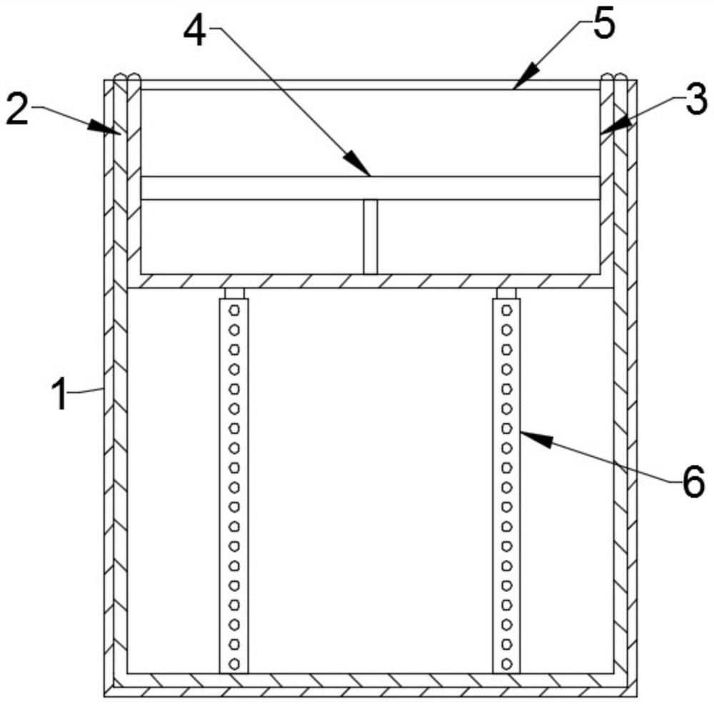
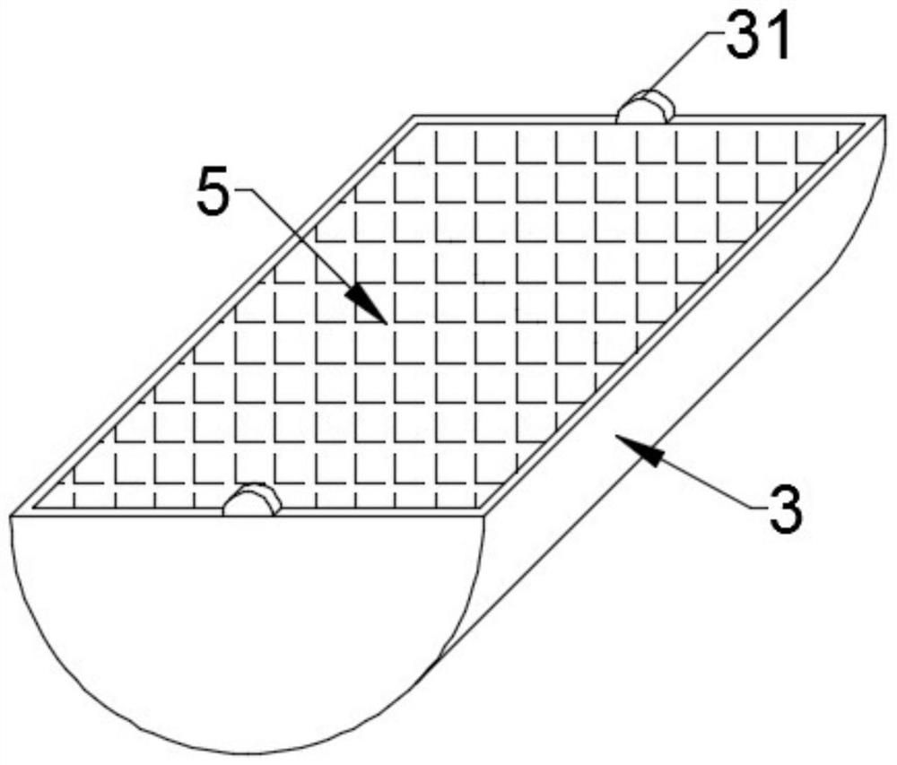
[0025] see Figure 1~4 , in an embodiment of the present invention, an embedded wide-angle adjustable floodlight includes a housing and a lamp body, and the housing includes an outer cylinder 1 and an inner cylinder 2 that are fitted through screw fits and movable sockets, and the inner cylinder 2. There is a cuboid through hole inside, and the upper part of the cuboid through hole is movably equipped with a lamp body. The lower end of the lamp body is symmetrically connected with a support rod 6 for vertical telescopic limit. The lamp body and the two sets of support rods 6 are all rotatably connected by a connecting mechanism with relative sliding fit and elastic limit.

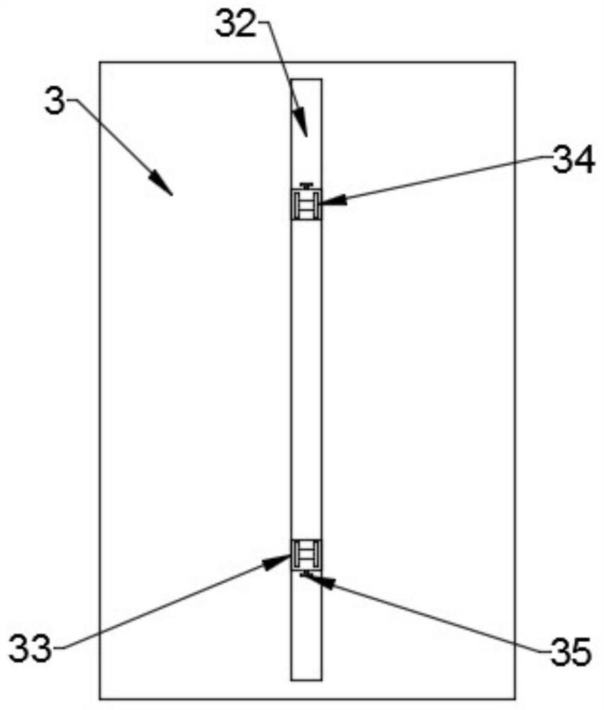
[0026] The lamp body includes a lamp housing 3 and an illuminating lamp 4. The lamp housing 3 is a semi-cylindrical cavity structure with an opening matching the size of the upper opening of the inner cylinder 2. The illuminating lamp 4 is installed on the lamp housing 3 Inside, the opening of the lamp hou...

Embodiment 2

[0032] see Figure 5 , in an embodiment of the present invention, an embedded wide-angle adjustable floodlight, on the basis of Embodiment 1, the support rod 6 includes a fixed sleeve 61 symmetrically fixed to the inner bottom of the inner cylinder 2, and the fixed sleeve The sleeve 61 is slidably fitted with a sliding support rod 62 , the sliding support rod 62 is rotatably connected to the hinge seat 34 , and the fixing sleeve 61 is provided with a plurality of sets of limiting holes 63 symmetrically on both sides. Sliding blind holes 64 are embedded symmetrically on both sides of the sliding support rod 62. The opening of the sliding blind holes 64 is the same as the diameter of the limiting hole 63. The sliding blind holes 64 are slidingly fitted with limiting pins 65. A compression spring is connected between one end of the limit pin 65 and the inner bottom of the sliding blind hole 64, and the other end of the limit pin 65 is hemispherical, and the hemispherical end is m...


PUM


Abstract

The invention discloses an embedded wide-angle adjusting type floodlight, and the floodlight comprises a shell and a light body; the shell comprises an outer barrel and an inner barrel which are movably connected in a sleeving mode through thread fit, a cuboid through hole is formed in the inner barrel, and the light body is arranged on the upper portion of the cuboid through hole in a movable fitmode; supporting rods used for vertical telescopic limiting are symmetrically connected to the lower end of the lamp body, and the lamp body and the two sets of supporting rods are rotationally connected through connecting mechanisms which are in relative sliding fit and are elastically limited. The inner barrel is rotated, so lifting of the inner barrel is achieved, the inner barrel can rotate while the height is increased, the irradiation position and the irradiation angle of the lamp body can be conveniently controlled, the height change is matched with the connecting mechanism arranged onthe lamp shell, the wide-angle adjusting effect can be achieved, and flexible control over the irradiation angle is effectively improved.

Description

technical field [0001] The invention relates to the technical field of floodlights, in particular to an embedded wide-angle adjustable floodlight. Background technique [0002] Flood lighting refers to a lighting method that makes a specific lighting area or a specific visual target much brighter than other targets and surrounding areas. In aircraft cockpit lighting, it refers to the lighting state of a large area such as the dashboard illuminated by floodlights. It is often used in the lighting design of advertisements or shop windows. It is also commonly used as auxiliary lighting and emergency lighting. [0003] Floodlight lamps used for floodlighting are generally composed of brackets or shells with lighting lamps. It is also not easy to pack, and these lamps are exposed on the ground and other positions, and are easily damaged. Contents of the invention [0004] The object of the present invention is to provide an embedded wide-angle adjustable floodlight to solve...

Claims


Application Information

Patent Timeline
IPC IPC(8): F21S8/00F21V21/30F21V21/36F21V15/01F21V19/00
CPCF21S8/00F21V21/30F21V21/36F21V15/01F21V19/00
Inventor 徐连城李隆
Owner 宏泰智能科技(东莞)有限公司
Learn More