Multifunctional universal water spraying device for cloth dyeing machine

A water-spraying device and multi-functional technology, applied in the field of dyeing machines, can solve the problem that the nozzle holder and the nozzle are not common, etc.

Active Publication Date: 2020-11-03
无锡市天东机械制造有限公司
View PDF5 Cites 0 Cited by
  • Summary
  • Abstract
  • Description
  • Claims
  • Application Information

AI Technical Summary

Problems solved by technology

[0004] In order to solve the problem that the nozzle seat and the nozzle are not universal, the application provides a multifunctional universal water spray device for a cloth dyeing machine

Method used


Image

  • Multifunctional universal water spraying device for cloth dyeing machine
  • Multifunctional universal water spraying device for cloth dyeing machine
  • Multifunctional universal water spraying device for cloth dyeing machine

Examples


Embodiment 1

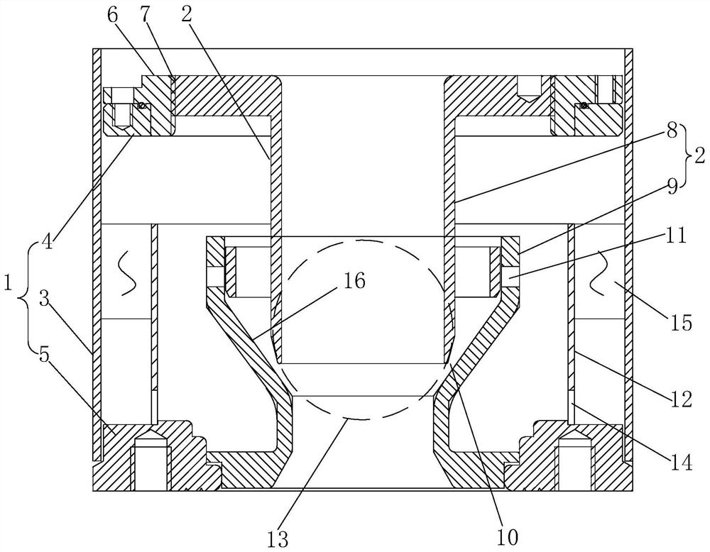
[0030] refer to figure 1 , including a nozzle seat 1 and a nozzle 2, the nozzle seat 1 is composed of a casing 3, a first annular block 4, and a second annular block 5, the casing 3 is in the shape of a cylinder with two ends open, and the first annular block 4 is fixed on the bottom of the casing 3 One end, the second annular block 5 is fixed on the other end of the shell 3, the nozzle 2 is installed in the shell 3, between the first annular block 4 and the second annular block 5, the first annular block 4, the second annular block 5, the nozzle 2 are all coaxial with the shell 3.

[0031] Such as figure 1 As shown, the side wall of the casing 3 has a circular water inlet 13, and the water inlet 13 is connected to the water pipe. An inner sleeve 12 is also fixed inside the casing 3 , the inner sleeve 12 surrounds the nozzle 2 and is coaxial with the nozzle 2 , and the bottom of the inner sleeve 12 is fixed on the second ring block 5 . The side wall of the inner sleeve 12 h...

Embodiment 2

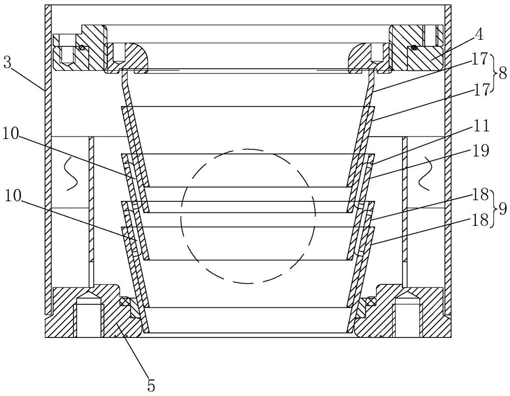
[0037] refer to figure 2 , The difference between this embodiment and Embodiment 1 is that the shapes of the inner insert 8 and the outer sleeve 9 are different, and a third frustum-shaped sleeve 19 is coaxially sleeved between the inner insert 8 and the outer sleeve 9 .

[0038] Such as figure 2 As shown, the inner insert 8 of this embodiment is composed of a first frustoconical sleeve 17 that is socketed in two layers, and the outer sleeve 9 is composed of a second frustoconical sleeve 18 that is socketed in two layers. The first frustoconical sleeve 17 And the tip of the second frustum-shaped sleeve 18 all points to the second annular block 5 .

[0039] Such as figure 2As shown, the third truncated cone sleeve 19 is also provided with threaded holes 11 for installing screws, and the screws on the outer sleeve 9 are used to withstand the outer wall of the third truncated cone sleeve 19, and the screws on the third truncated cone sleeve 19 Screws are used to butt agains...


PUM


Abstract

In order to solve the problem that a nozzle holder and a nozzle are not universal, the invention provides a multifunctional universal water spraying device for a cloth dyeing machine. The invention relates to the field of cloth dyeing machines, in particular to the multifunctional universal water spraying device for the cloth dyeing machine. The multifunctional universal water spraying device comprises a nozzle holder and a nozzle, the nozzle holder comprises a shell, the shell is in a cylinder shape with two communicated ends, the nozzle is arranged in the shell, a water inlet is formed in the shell, and a first annular block and a second annular block which are coaxial are arranged in the shell. A pressing disc is coaxially arranged on the first annular block, and a center hole is formedin the pressing disc. The nozzle comprises an inner inserting piece and an outer sleeving piece which are coaxial, the inner inserting piece is inserted into the outer sleeving piece, a pressurizinghole is defined by the inner inserting piece and the inner wall of the outer sleeving piece, a threaded hole is formed in the outer sleeving piece and used for being in threaded connection with a screw, the screw is used for abutting against the outer wall of the inner inserting piece, the inner inserting piece is in threaded connection with the inner wall of the center hole, and the outer sleeving piece abuts against the second annular block.

Description

technical field [0001] The present application relates to the field of cloth dyeing machines, in particular to a multifunctional universal water spray device for cloth dyeing machines. Background technique [0002] A general cloth dyeing machine includes structures such as nozzles and cloth storage tanks, so that the cloth circulates in the cloth dyeing machine in a continuous rope-like manner. There are many types of nozzles, and the actual selection is based on the customer's production fabric, production process and operating habits. [0003] In the related technology, each nozzle must be used in conjunction with the corresponding nozzle seat (that is, the nozzle seat is installed in the cloth dyeing machine, and the nozzle is installed on the nozzle seat), resulting in high cost when dyeing multiple types of cloth; and each replacement When using the nozzle, the nozzle seat must also be changed, resulting in shortened production hours and reduced production efficiency. ...

Claims


Application Information

Patent Timeline
IPC IPC(8): D06B1/02D06B23/20
CPCD06B1/02D06B23/20
Inventor 张子伟杨年杰姚旭东
Owner 无锡市天东机械制造有限公司
Why Eureka
Try Eureka