
Patsnap Eureka
For R&D, Patsnap Eureka makes reading and utilizing patents & technical documents easy.
Patsnap Eureka AIR
Designed for self-driven R&D workflows. Generate viable solutions, solve complex R&D challenges, empower your innovation with AI.

Patsnap Eureka Materials
Designed for material experts only. Revolutionize your material R&D, from search, analyze, to developing new materials.

TechResearch
Generate reliable direction feasibility study reports for your R&D in just a few steps.

TechSeek
Discover and master advanced knowledge NOW. Basics, ideas, possibilities, all at once.

TechMind
As an expert in R&D Theories, TechMind can generates customized viable solutions instantly.

TechRisk
Analyze your overall solution with one click, know your potential R&D risks in advance.

TechMonitor
Get weekly tech updates, stay abreast of the latest tech innovations and key insights.
Camera module detection method and device, electronic equipment and medium
A technology of camera module and detection method, applied in branch equipment, TV, electrical components, etc., can solve the problems of inconspicuous bad phenomenon, difficult to detect accurately, easy to miss detection, etc., and achieve the effect of improving the yield of the factory
- Summary
- Abstract
- Description
- Claims
- Application Information
AI Technical Summary
Problems solved by technology
Method used
Image


Examples
Embodiment 2
[0108] Such as Figure 8 As shown, a camera module detection device is provided, including:
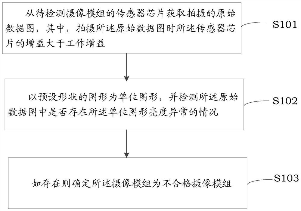
[0109] An acquisition module 801, configured to acquire a captured raw data map from the sensor chip of the camera module to be detected, wherein the gain of the sensor chip is greater than the working gain when the raw data map is taken;
[0110] A detection module 802, configured to use a graph of a preset shape as a unit graph, and detect whether there is an abnormal brightness of the unit graph in the original data graph;
[0111] A determining module 803, configured to determine that the camera module is an unqualified camera module if it exists.
[0112] In the embodiment of the present application, the camera module detection device may be a camera module, a computer, a dedicated tester or a test device integrated into the production line, which is not limited here.
[0113] Since the device introduced in Embodiment 2 of the present invention is the device used to implement t...
Embodiment 3
[0116] Such as Figure 9 As shown, the present embodiment provides an electronic device, including a memory 910, a processor 920, and a computer program 911 stored in the memory 910 and operable on the processor 920. When the processor 920 executes the computer program 911 Implement the following steps:
[0117] Obtain the captured raw data map from the sensor chip of the camera module to be detected, wherein the gain of the sensor chip is greater than the working gain when shooting the raw data map;
[0118] Taking a graph with a preset shape as a unit graph, and detecting whether there is an abnormal brightness of the unit graph in the original data graph;
[0119] If it exists, it is determined that the camera module is an unqualified camera module.
[0120] In this embodiment of the present invention, when the processor 920 executes the computer program 911, any implementation manner in Embodiment 1 of the present invention may be implemented.
[0121]Since the electron...
Embodiment 4
[0124] This embodiment provides a computer-readable storage medium 1000, such as Figure 10 As shown, a computer program 1011 is stored thereon, and it is characterized in that, when the computer program 1011 is executed by the processor, the following steps are implemented:
[0125] Obtain the captured raw data map from the sensor chip of the camera module to be detected, wherein the gain of the sensor chip is greater than the working gain when shooting the raw data map;
[0126] Taking a graph with a preset shape as a unit graph, and detecting whether there is an abnormal brightness of the unit graph in the original data graph;
[0127] If it exists, it is determined that the camera module is an unqualified camera module.
[0128] In a specific implementation process, when the computer program 1011 is executed by a processor, any implementation manner in Embodiment 1 of the present invention may be implemented.
PUM
 Abstract
Description
Claims
Application Information
 - R&D Engineer
- R&D Manager
- IP Professional
- Industry Leading Data Capabilities
- Powerful AI technology
- Patent DNA Extraction
Browse by: Latest US Patents, China's latest patents, Technical Efficacy Thesaurus, Application Domain, Technology Topic, Popular Technical Reports.
© 2024 PatSnap. All rights reserved.Legal|Privacy policy|Modern Slavery Act Transparency Statement|Sitemap|About US| Contact US: help@patsnap.com